Fire detector

a detector and detector technology, applied in the field of fire detectors, can solve the problems of reducing the s/n ratio, difficult to prepare an adequate smoke detection area, and shortening the distance between the light emitting element and the light detecting element,

Inactive Publication Date: 2001-02-27
LIXIL NITTAN
View PDF14 Cites 13 Cited by
  • Summary
  • Abstract
  • Description
  • Claims
  • Application Information

AI Technical Summary

Benefits of technology

According to the present invention, because the axis of the light emitting element crosses the axis of the light detecting element along with a vertical direction, it is possible to miniaturize the fire detector in a horizontal direction. Further, because the light emitting element is arranged in the projecting portion, the distance between the axis of the light detecting element and the light emitting element can be prepared well, for example, in comparison with a case that the light emitting element and the light detecting element are arranged in the vertical direction by using the circular smoke chamber. Therefore, the large smoke detecting area can be prepared.
According to the present, because both edge sides of the insect screen, which have the predetermined width is not etched, a high bending strength of the insect screen is achieved. Therefore, the insect screen can be bent into deformed shapes easily and can be applied to any types of fire detectors having various shapes.

Problems solved by technology

However, in case that a fire detector having such a structure identified above is miniaturized, it is difficult to prepare an enough smoke detecting area because it is inevitable to shorten a distance in a radial direction, and then a distance between the light emitting element and the light detecting element becomes shorter.
Such a reflected light is detected by the light detecting element as a noise light, and a problem including a decrease of an S / N ratio occurs.

Method used


Image

  • Fire detector
  • Fire detector
  • Fire detector

Examples


Embodiment Construction

Hereinafter, an embodiment of the invention will be explained in view of drawings.

FIGS. 1A to 1C show an appearance of a fire detector 1 according to the present invention. As shown in FIGS. 1A to 1C, a casing of the fire detector 1 comprises an upper case 2 and a base 3.

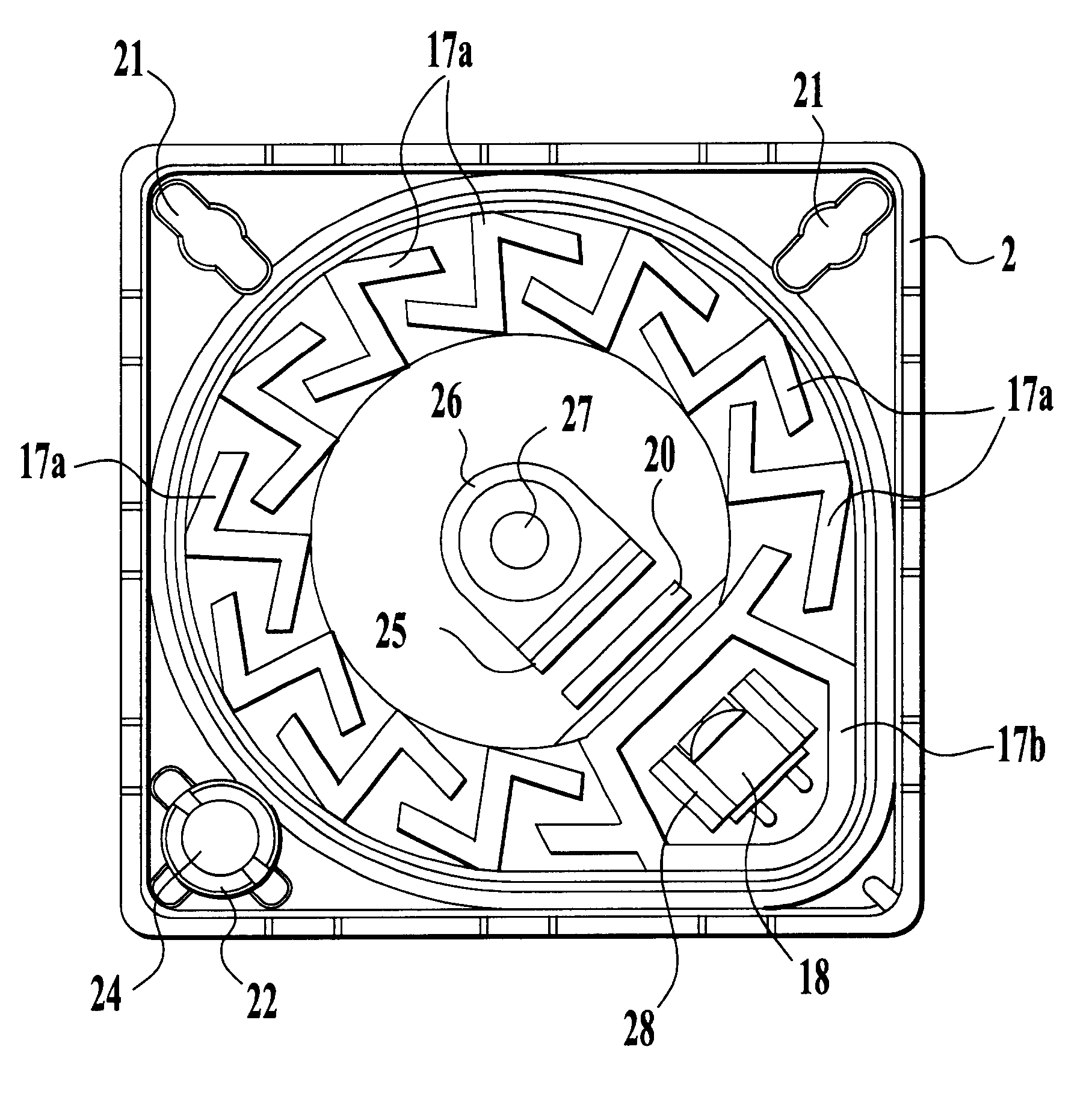
When a light emitted by the light emitting element is scattered by an inflow of a smoke caused by a fire, the scattered light is detected by the light detecting element. Then, the fire detector senses a fire.

The fire detector 1 is equipped on the ceiling so that a surface shown in FIG. 1A faces to a floor. In this embodiment, the fire detector 1 will be explained by defining a side close to the floor as an upper part and a side close to the ceiling as a lower part when the fire detector is equipped.

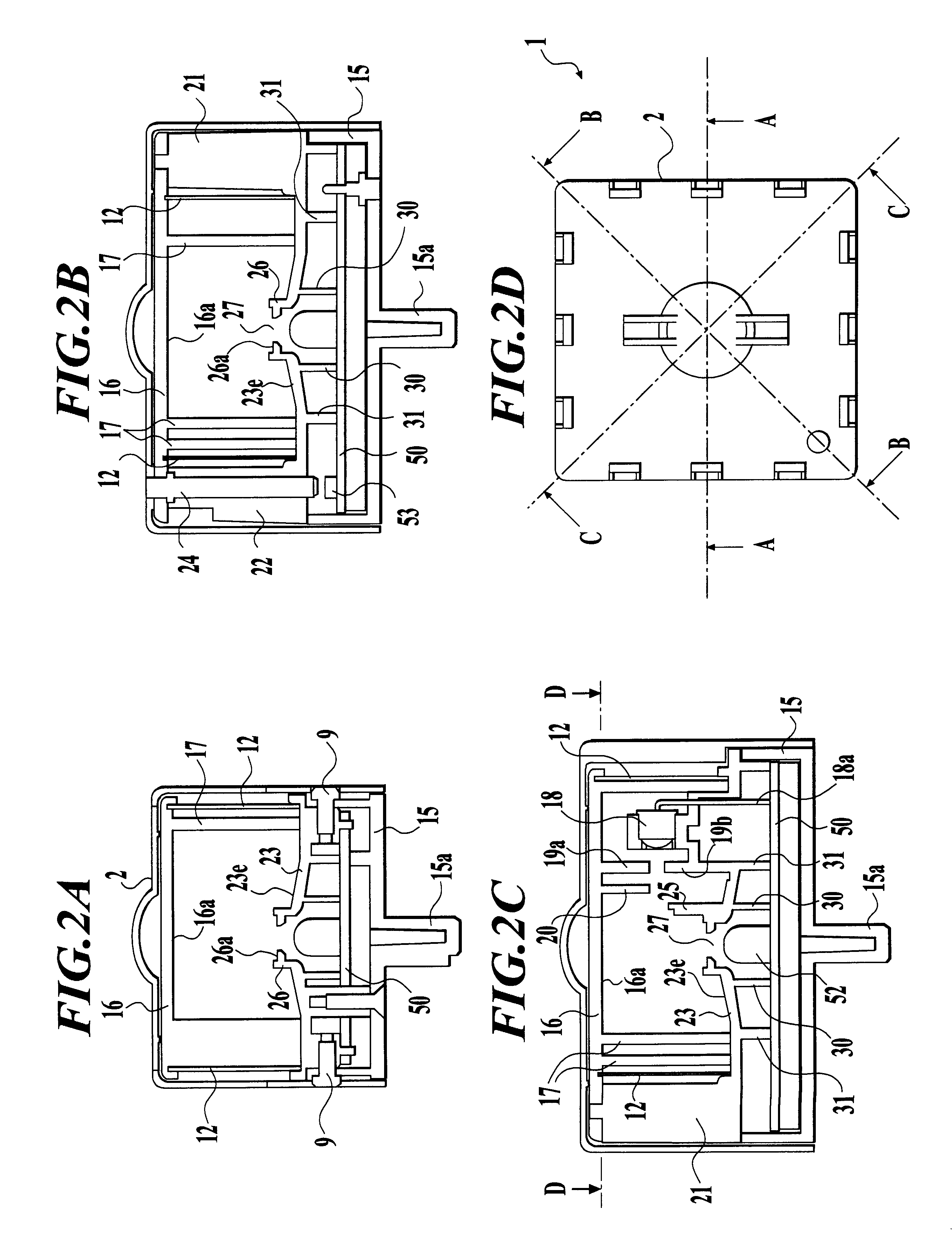
Firstly, a main body 10 which is contained into the upper case 2, is explained. FIGS. 2A to 2C show the inner side of the fire detector 1 and FIG. 2D shows a plan view of the fire detector 1 from an upper position thereof...


PUM


Abstract

The fire detector for sensing a fire, comprises; a smoke chamber, a light emitting element, and a light detecting element for detecting a scattered light caused by scattering a light emitted by the light emitting element with a smoke which enters in the smoke chamber, wherein a wall part of the smoke chamber is formed in a shape based on a circle having a predetermined size, and comprises a projecting portion which projects from at least a part of the circle to an outside of the circle, the light emitting element is disposed on the projecting portion of the smoke chamber, and the light detecting element is arranged out of the smoke chamber and an optical axis thereof is approximately perpendicular to a plane including the circle.

Description

1. Field of the InventionThe present invention relates to a fire detector for sensing a fire by detecting a smoke caused by the fire.2. Description of Related ArtAccording to an earlier development, a smoke-detecting type of the fire detector which senses a fire by detecting a smoke caused by the fire by using a light emitting element and a light detecting element is often attached to one member having a disk shape so that the light emitting element is placed at a certain angle with respect to the light detecting element, for example as described in Japanese Patent Application No. Tokukai-Hei 8-166347.However, in case that a fire detector having such a structure identified above is miniaturized, it is difficult to prepare an enough smoke detecting area because it is inevitable to shorten a distance in a radial direction, and then a distance between the light emitting element and the light detecting element becomes shorter.Contrarily, a fire detector as described in Japanese Patent A...

Claims


Application Information

Patent Timeline
IPC IPC(8): G08B17/107G08B17/103G08B17/10G01N21/53
CPCG08B17/107G08B17/113
Inventor SAKURAI, KAZUYOSHITSUBOUCHI, SEIJI
Owner LIXIL NITTAN
Why Eureka
Try Eureka