
Device fitted on vehicles for monitoring tyre pressure

a technology for monitoring devices and tyres, which is applied in the direction of tyre measurement, electrical equipment, electric switches, etc., can solve the problems of increasing the thickness of the cable harness in the chassis cavity, increasing the difficulty of adjusting the thickness of the cable harness, and increasing the cost of the undertaking

Inactive Publication Date: 2001-02-27
UHL GUNTER +4
View PDF6 Cites 58 Cited by
  • Summary
  • Abstract
  • Description
  • Claims
  • Application Information

AI Technical Summary

Benefits of technology

In the vicinity of each wheel, only an antenna is provided, and all antennas are connected with a common electronic receiving and evaluating circuitry. An antenna cable is required to connect the antenna in the wheel housing with the receiving circuitry which may be located anywhere in a central location in the vehicle chassis, for example, in the dashboard area. The antenna cables need not be installed individually, which would be an expensive undertaking, but instead can be combined with other cables which need to be installed in the vicinity of the wheel anyway, to form a cable harness which can be prefabricated.
It is especially advantageous if, instead of installing a dedicated antenna cable, an electric cable is used as an antenna which needs to be installed anyway and belongs to another monitoring device assigned to the same wheel, in particular, a device monitoring brake lining wear of the wheel in question, or an ABS system, or a type of control device which prevents driven wheels from slipping. This would minimize circuitry cost, susceptibility to breakdown, and reduce cabling cost, because of the multiple use of an electric cable installed to each wheel area. This latter point is particularly important, because in the past few years the number of vehicle functions monitored, controlled and operated has steadily increased making it more and more difficult to accommodate the ever increasing cable harness thickness in the chassis cavities. The multiple use of an electric line allows each wheel to have its own antenna without increasing the cabling cost for signal transmission from the transmitter to the receiving and evaluating circuitry.
Naturally the cable must be suitable as an antenna for the intended frequency range. The frequencies needed for transmission are in the range of several hundred MHz, especially 433 MHz. Since the frequencies customarily used for ABS and ASR applications are not more than a few kHz and the brake liner wear display is performed in the low frequency range or with direct current, the high frequency signals used for monitoring tire pressures and the low frequency signals used for other monitoring functions can be easily combined in and again separated from one common line.

Problems solved by technology

This is an expensive solution, since the signals which are emitted by the transmitter located in a particular wheel and which contain the air pressure determined by the pressure sensor, are each transmitted wirelessly to a separate transmitting and receiving device assigned to each wheel.
The antenna cables need not be installed individually, which would be an expensive undertaking, but instead can be combined with other cables which need to be installed in the vicinity of the wheel anyway, to form a cable harness which can be prefabricated.
This latter point is particularly important, because in the past few years the number of vehicle functions monitored, controlled and operated has steadily increased making it more and more difficult to accommodate the ever increasing cable harness thickness in the chassis cavities.

Method used


Image

  • Device fitted on vehicles for monitoring tyre pressure
  • Device fitted on vehicles for monitoring tyre pressure
  • Device fitted on vehicles for monitoring tyre pressure

Examples


Embodiment Construction

In the various figures identical or corresponding components are designated with the same reference numbers.

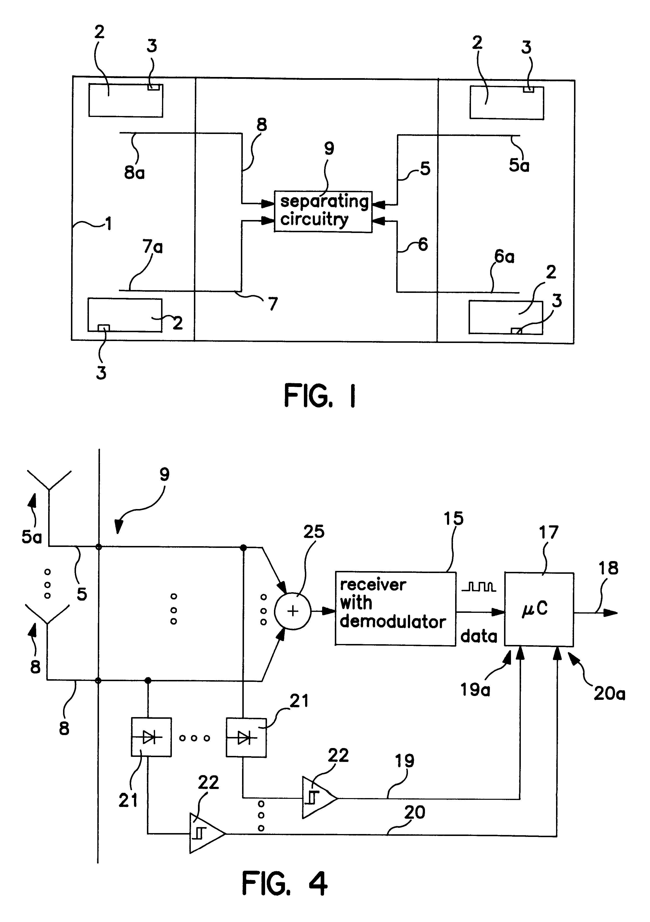
FIG. 1 shows schematically the plan view of the chassis 1 of a vehicle with four wheels 2, each of which is equipped with an arrangement 3 consisting of a pressure sensor and a transmitter. An antenna 5a, 6a, 7a, 8a is assigned to each wheel 2. The antennas are formed by a section of a co-axial cable 5, 6, 7, 8 which is stripped of its outer conductor so that the inner conductor of the co-axial cable in this section 5a, 6a, 7a, 8a is not shielded by the outer conductor, but can receive high-frequency signals. The co-axial cables 5, 6, 7, 8 are connected to a separating circuitry 9 shown in FIG. 3. The length of the sections 5a, 6a, 7a, 8a is conveniently made equal to one quarter of the wave length of the frequency transmitted by the transmitter provided in arrangement 3; for a frequency of 433 MHZ, this length is 17 cm.

The exemplary embodiment shown in FIG. 2 differs from tha...


PUM


Abstract

The proposed device is fitted on vehicles equipped with pneumatic tires and is used for monitoring tire pressure. The device comprises: a pressure measurement sensor on each of the wheels (2) being monitored; a transmitter mounted next to each pressure measurement sensor which emits signals carrying the pressure data obtained from the pressure measurement sensor, and a receiver for those signals fitted on the vehicle chassis. An antenna (5a, 6a, 7a, 8a) is arranged next to each wheel (2) as the receiver. The antennae are connected to a common receiving and monitoring circuit (15, 17).

Description

1. Field of the InventionThe invention deals with a device fitted on vehicles for monitoring the air pressure in the vehicle's tires.2. Discussion of the Prior ArtIn known devices for monitoring the air pressure in the tires of a vehicle, pressure sensors are arranged in the wheels and each pressure sensor is connected with a transmitter. Here, an antenna is positioned in the vicinity of each wheel and the antennas are connected with a common receiving and evaluating circuitry. The transmitters provided in the wheels are not synchronized with each other. Therefore, it is possible that the signal strings coming from the various wheels overlap at the input side of the receiving and evaluating circuitry, thereby preventing unambiguous evaluation. This difficulty has previously been resolved where the disclosed device for monitoring the tire pressure is provided with a pressure sensor and a transmitter, which are integrated in the valve cap of each wheel in the form of an electronic ass...

Claims


Application Information

Patent Timeline
IPC IPC(8): B60C23/04B60C23/02
CPCB60C23/0433B60C23/0437B60C23/0444
Inventor UHL, GUNTERNORMANN, NORBERTSCHULZE, GUNTER LOTHARKESSLER, RALPHSCHROTTLE, MICHAEL
Owner UHL GUNTER
Learn More