
Apparatus for automatically conveying cartridges

a technology of automatic conveying and cartridges, applied in the direction of ignition automatic control, electric controllers, instruments, etc., can solve the problems of not being able to automatically convey cartridges, requiring unattended operation, and requiring laborious work as well as considerable expens

Inactive Publication Date: 2001-02-06
FUJITSU LTD
View PDF9 Cites 13 Cited by
  • Summary
  • Abstract
  • Description
  • Claims
  • Application Information

AI Technical Summary

Problems solved by technology

Moreover, incorporating a mechanical unit in the apparatus for automatically conveying cartridges maintaining precision requires laborious work as well as considerable expense.
As the apparatus is designed to operate automatically, furthermore, it is required to operate unattended.
Even when the apparatus for automatically conveying cartridges is coupled to a library unit to automatically convey the cartridges, however, it is not possible to automatically convey the cartridges when there are included cartridges from which the leader block has been pulled out or when the detector mechanisms have been broken in the apparatus for automatically conveying the cartridges.
When the power source circuit is closed or an error has occurred, however, the accessor 8 is not initialized.
The conventional apparatus has not been equipped with a function for automatically discriminating a new ACL apparatus or an old ACL apparatus.
This makes it difficult to determine the number of the cartridges by the software that manages the library unit 12.
However, an extended access time is required since the retrying is effected each time.
3 When the rack and the accessor 8 are deviated from each other, the cartridge is not taken out from the rack or the cartridge is not returned back to the rack, resulting in an error.
When such an event occurs in the batch job during the night, however, the processing must be interrupted.
Therefore, the processing is interrupted during this period often resulting in a tremendous amount of damage.
When the leader block has been pulled out, therefore, there arises a problem in that the cartridge cannot be loaded into the library unit 12 when the cartridge is taken out from the exit cell 14 in the ACL apparatus 5 for attachment to a library unit and is loaded into the MTU (MTU in the library unit 12) which is not prepared to cope with the cartridges into which the leader block has not been pushed.
Therefore, overrunning of a predetermined amount is not accomplished.
Therefore, the accessor 8 ascends or descends in a state where the cartridge has been missed or the cartridge has not been properly held in the accessor 8, causing the cartridge to be broken or the apparatus to be damaged.
Despite the feeder mechanism being retried, therefore, the cartridge is neither fed nor returned, and an error occurs.
In the conventional control operation, therefore, there is no guarantee that the cartridge has returned back to the rack, and there remains a possibility that the cartridge is erroneously recognized to have returned back to the rack though it has not really returned back to the rack due to some obstacle like damage to the motor.
There remains a problem in that if the LED of the operator panel breaks, it becomes difficult to determine whether the cartridge is the one that has not been processed or not.
When the data related to the types of the apparatuses are to be set, however, the operation involves mistakes, and the operator must set the data again requiring a cumbersome operation.
Furthermore, when the two firmwares are employed, i.e., when the respective firmwares are input to different apparatuses, it becomes impossible to operate the system and mistakes are inevitably involved in the operation.
When a cartridge exists on the rack of the exit cell, it is not possible to discharge the cartridge in the recording / reproducing apparatus (MTU 6).
However, if the presence-of-cartridge detector mechanism is not working properly, it may appear that the cartridge is present on the rack of the exit cell though it is really not present thereon.
When the cartridge was loaded onto the rack in an inclined manner, the cartridge, could not be detected and could not be processed.
Therefore, the feeder belts are not partly worn out but are entirely worn out.
When the cartridge that was being returned back to the rack was not detected by the detector mechanisms 1, 2 of the rack side, there was a probability that the cartridge may be missed even when it is not properly placed on the cell.

Method used


Image

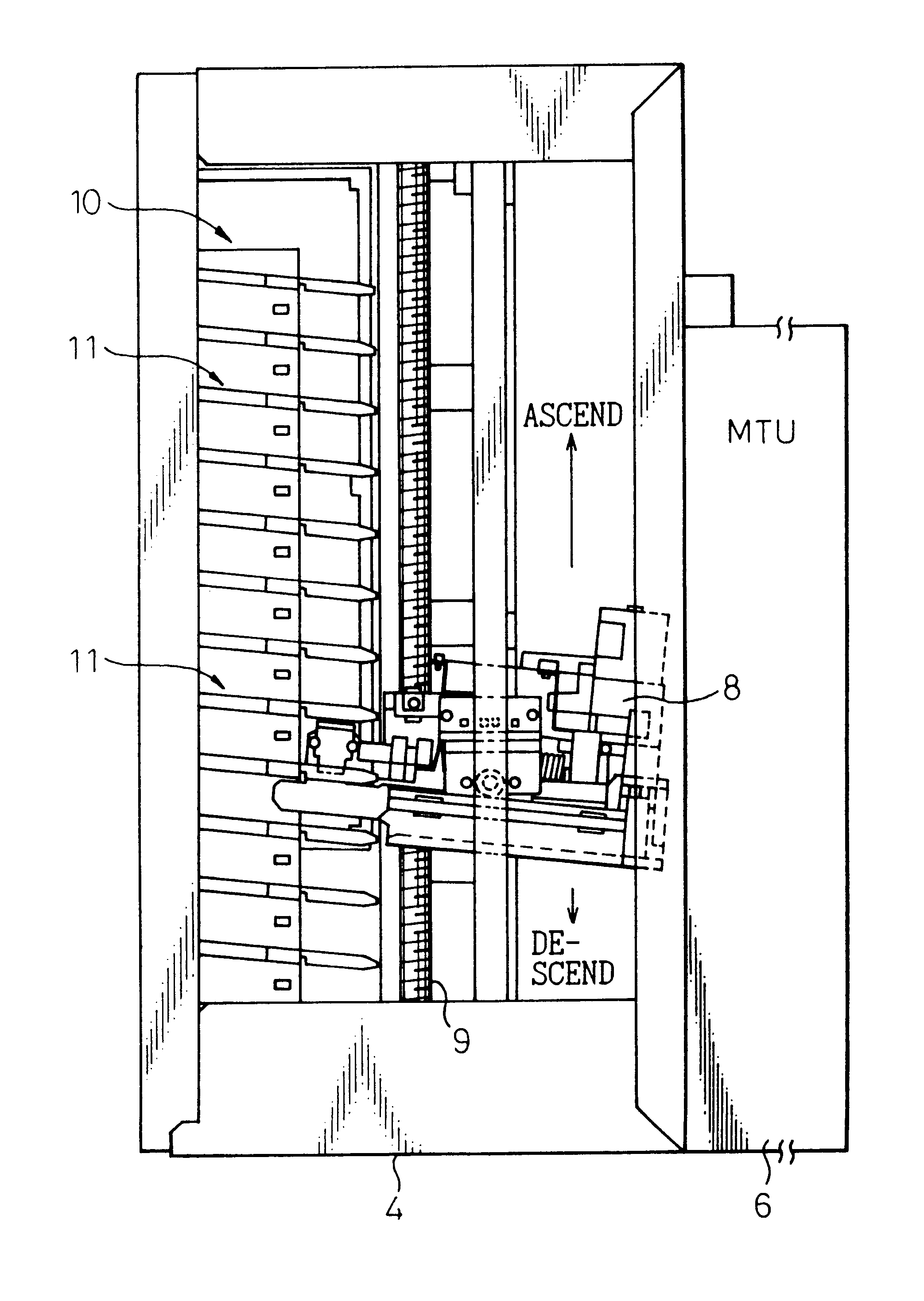
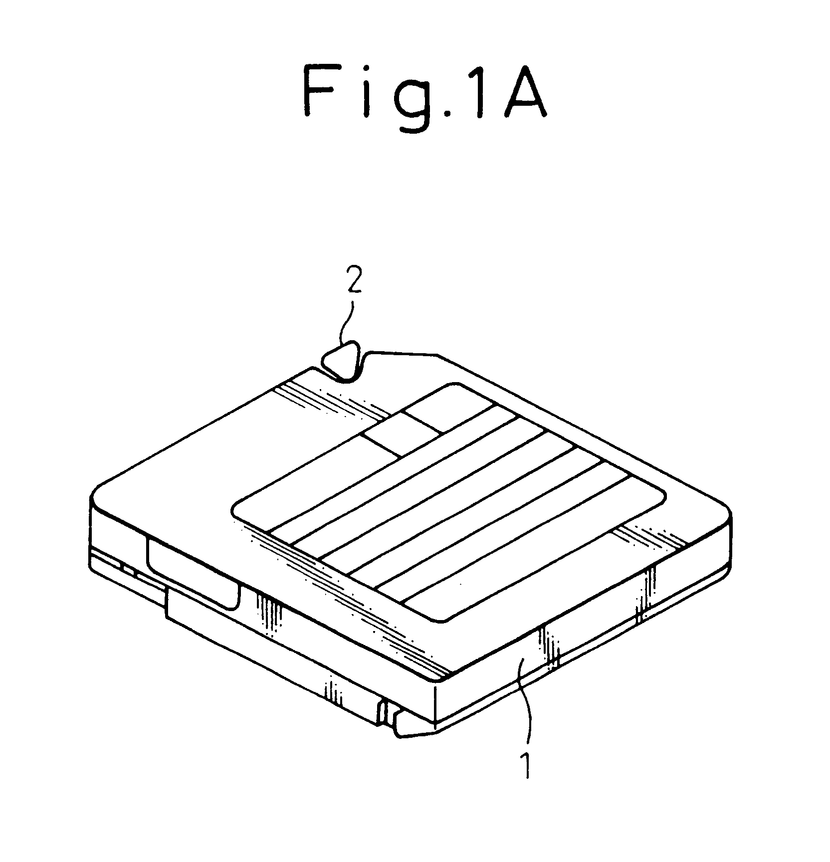
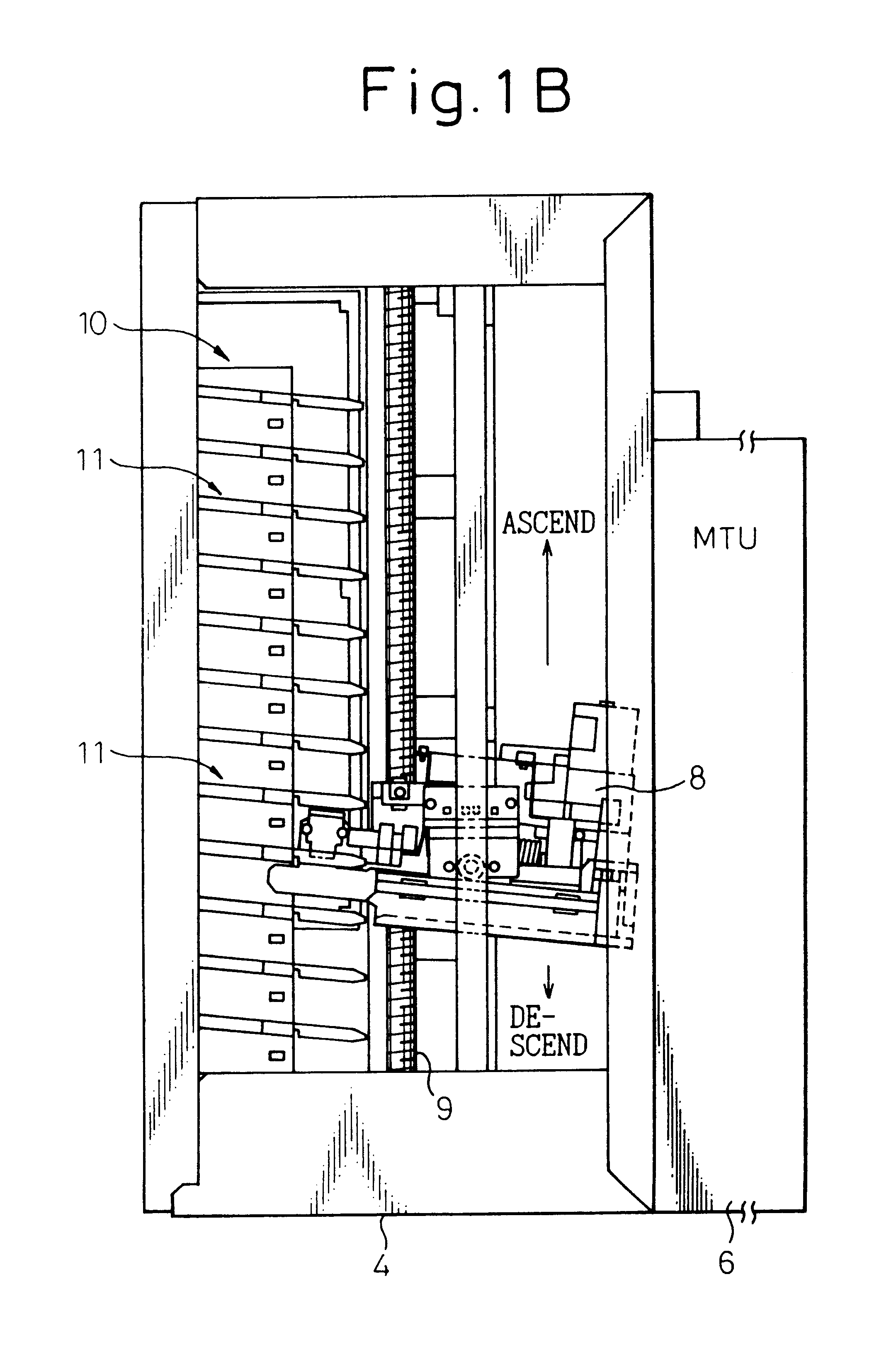
  • Apparatus for automatically conveying cartridges
  • Apparatus for automatically conveying cartridges
  • Apparatus for automatically conveying cartridges

Examples


Embodiment Construction

of the ACL Control Unit--see FIG. 22.

FIG. 22 is a detailed block diagram of an ACL control unit. The ACL control unit will now be described in detail with reference to FIG. 22.

The ACL control unit 81 includes an MPU 91, a memory 92 for communication, a ROM 93, a work memory 94, a motor control unit 95, a solenoid control unit 97, a sensor control unit 98, a power amplifier 82, a level comparator 83, a tachometer value latch circuit 100, a timer 106 and an EEPROM 107. The motor control unit 95 is provided with a PWM control unit 96 (PWM: pulse width modulation), and the EEPROM 107 stores a table of ideal values of rack positions. Described below are the functions of the above-mentioned portions.

(1) The MPU 91 executes a variety of control operations in the ACL apparatus.

(2) The memory 92 for communication is used for communication with the MPU 73 for ACL control.

(3) The ROM 93 is a nonvolatile memory storing various programs that will be executed by the MPU 91 and parameters.

(4) The ...


PUM


Abstract

An apparatus is automatically conveying cartridges reliably and correctly without causing errors, making it possible to enhance the operation efficiency and performance of the apparatus. The apparatus is automatically conveying cartridges disposed adjacent to a recording / reproducing apparatus, and is comprised of a cell mechanism having racks, an accessor mechanism having an accessor, and a conveyance control unit for controlling the conveyance of the cartridges by controlling the accessor mechanism, wherein the accessor is provided with catcher hands, a catcher hand drive mechanism, an open detector mechanism for detecting the open state of said catcher hands, and a closed detector mechanism for detecting the closed state of said catcher hand. The conveyance control unit is equipped with a catcher hand controller which controls the catcher hands to assume an open state, a closed state or a middle state which is an intermediate state relying upon the data detected by the open detector mechanism and the closure detector mechanism.

Description

1. Field of the InventionThe present invention relates to an apparatus for automatically conveying cartridges to a magnetic tape unit which records and reproduces data by using a magnetic cartridge tape (hereinafter simply referred to as "cartridge") as a recording medium.2. Description of the Related ArtIn recent years, automatic operation of magnetic tape units has become so advanced that it is necessary to employ an apparatus for automatically conveying cartridges to take a cartridge that is to be processed from a rack of a cell mechanism, in which a plurality of cartridges are stored, and to convey the cartridge to a magnetic tape apparatus.In the apparatus for automatically conveying cartridges, a robot that requires a servo control operation has generally been controlled by firmware. Furthermore, the torque required from a motor to drive the apparatus for automatically conveying cartridges varies depending upon the apparatuses due to mechanical tolerance, the environment in wh...

Claims


Application Information

Patent Timeline
IPC IPC(8): G11B15/68G11B17/22
CPCG11B15/6835G11B17/225
Inventor AKIYAMA, HITOMIAKIYAMA, YOSHIKI
Owner FUJITSU LTD
Learn More