
Centrifugal blood pump

a centrifugal and blood pump technology, applied in the direction of prosthesis, positive displacement liquid engine, liquid fuel engine, etc., can solve the problems of thrombosis at the inner bottom, difficult to completely seal the clearance between the rotation shaft and the casing, and insufficient blood fluidity

Inactive Publication Date: 2001-02-06
KYOCERA CORP +1
View PDF9 Cites 146 Cited by
  • Summary
  • Abstract
  • Description
  • Claims
  • Application Information

AI Technical Summary

Benefits of technology

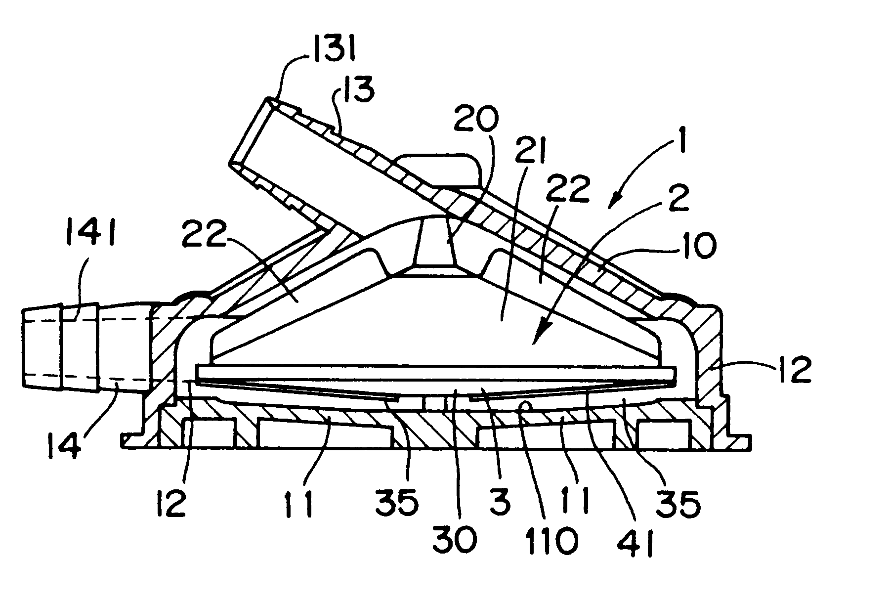
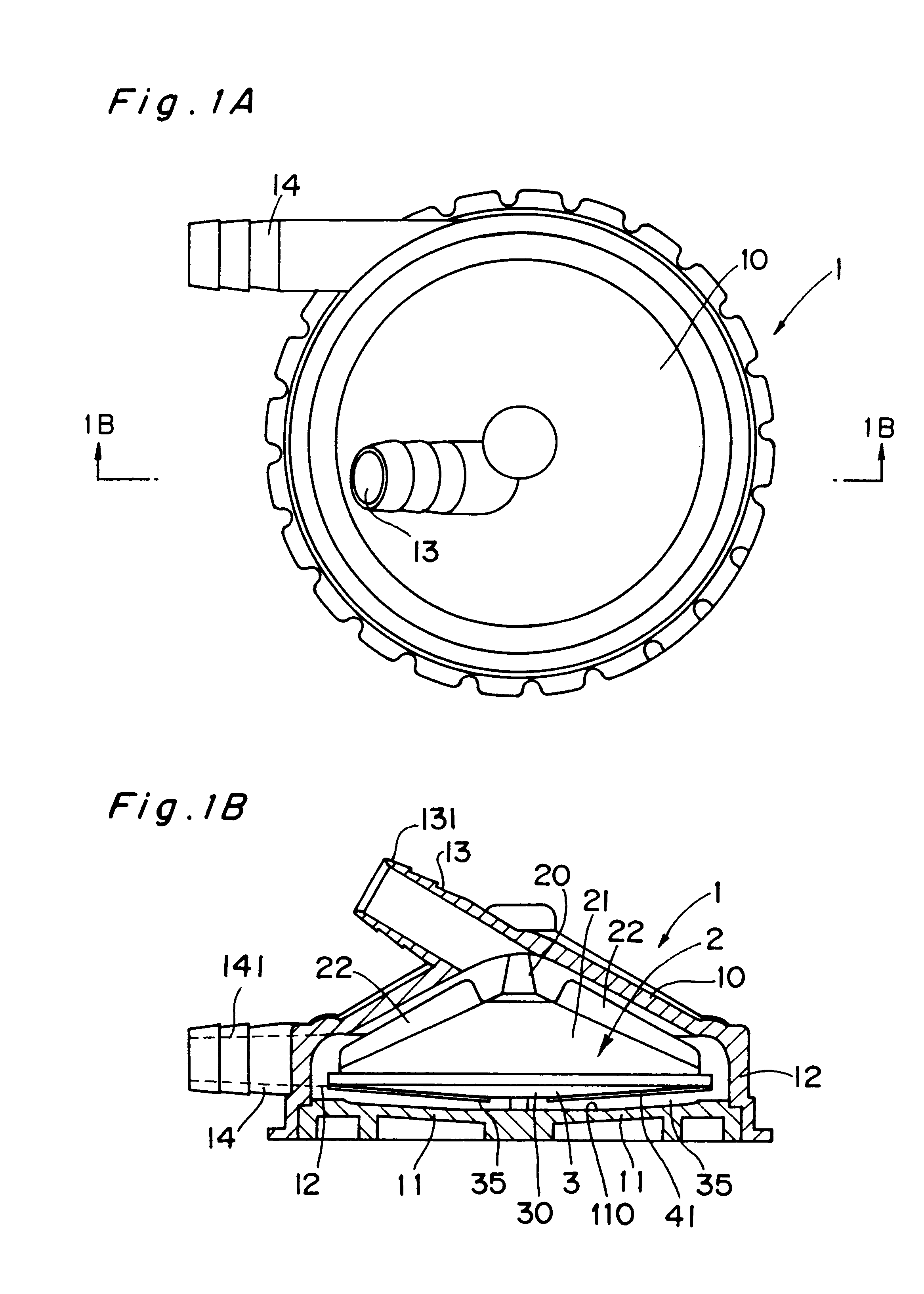
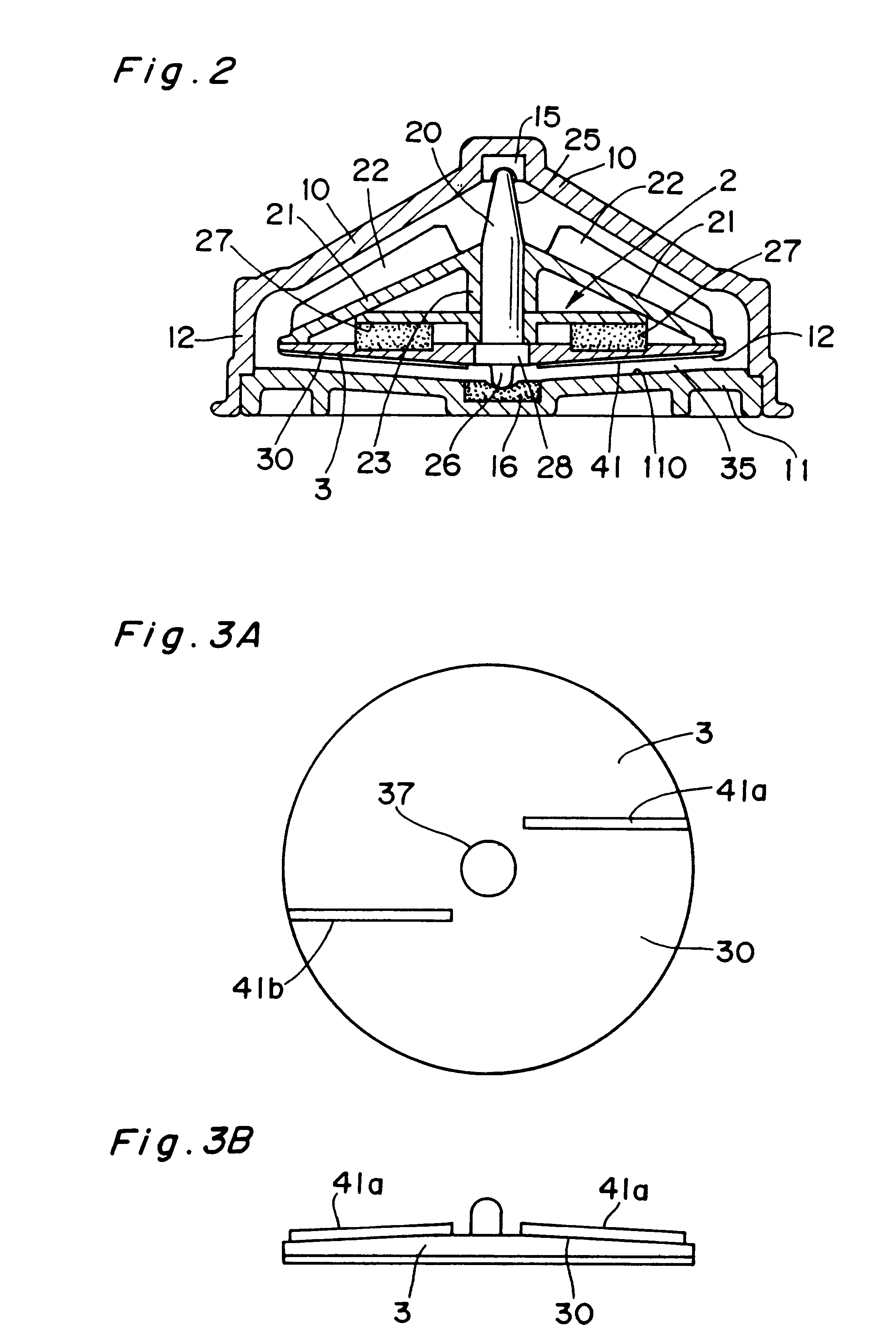
In the present invention, one or more stirring elements having the shape of a fin or a groove are formed on the bottom of the main impeller facing the inner bottom surface of the pump casing. In the invention, the dimensions, shape and positions of the fins or grooves used as the stirring elements are determined to completely prevent thrombus from attaching to the inner bottom portion of the casing without deteriorating the anti-hemolytic characteristic of blood.

Problems solved by technology

In the case of the above sealed type centrifugal blood pump, it is difficult to completely seal the clearance between the rotation shaft and the casing.
Furthermore, the seal-less type blood pump may also cause thrombus at the inner bottom portion of the casing on the opposite side of the suction inlet, although the pump has no sealing portion for the rotor of the impeller.
However, no sufficient blood fluidity was obtained by just forming the through holes in the seal-less pump, and thrombus was unable to be prevented.
However, this caused a problem of generating hemolysis, that is, hemocytes in blood passed through the pump were apt to be destructed.
However, hemocytes are apt to be destructed at the same time.
If the parameters are larger than the higher limits in the range, the stirring force is so excessive that the amount of hemolysis increases because of destructed hemocytes, whereby the anti-hemolytic characteristic of blood is impaired.

Method used


Image

  • Centrifugal blood pump
  • Centrifugal blood pump
  • Centrifugal blood pump

Examples


Embodiment Construction

In order to optimize stirring impellers 3 having the fins 41 and the stirring impeller 3 having the grooves 42 to prevent thrombus from generating and to prevent the antihemolytic characteristic of blood from lowering, tests were conducted in accordance with the following processes.

The impellers 3 having the fins 41 were produced so as to have the following dimensions: the diameter D of the impeller=65 mm, the length l of the fin 41=28 mm, the thickness t=1.6 mm, and the height h=1.0 mm. The number n of the fins 41 was 2 to 4. The outside shapes of these impellers 3 are shown in FIGS. 5A to 5C.

The impellers 3 having the grooves 42 were produced having the following dimensions: the diameter D of the impeller=65 mm, the length l of the groove=28 mm, the width w thereof=0.6 mm, and the depth d thereof=0.08 mm. The number n of the grooves 42 was 2 to 4. The outside shapes of these impellers 3 are shown in FIGS. 6A, 6C and 6D.

The parameters L / D and S / A for the impellers having the fins a...


PUM


Abstract

The present invention provides a blood pump capable of substantially completely preventing thrombus from attaching to the inner bottom portion of the casing without lowering the anti-hemolytic characteristic of blood. A centrifugal blood pump in accordance with the present invention comprises a pump casing, a suction inlet disposed at the central portion on the upper side of the casing, a delivery outlet disposed at the bottom peripheral portion of the casing, a main impeller (D in diameter) for forming a centrifugal flow of blood supplied from the suction inlet in the range from the central portion to the peripheral portion to feed the blood to the delivery outlet, wherein the main impeller is provided with an stirring impeller, the surface of which is provided with one or more stirring elements (L in entire length) having the shape of a fin or a groove, and the dimensions of the stirring elements are determined to satisfy inequality (1): 0.43<LD<1.30 and inequality (2) 0.03<S / A<0.21, where S is the surface area of the blood contact surfaces of the stirring elements.

Description

The present invention relates to a blood pump used for artificial auxiliary hearts and heart-lung machines, and more particularly to a blood pump capable of preventing thrombus from attaching to the interior thereof.PRIOR ARTConventionally, a centrifugal pump has been used as a blood pump. The centrifugal pump comprises a conical impeller for generating a centrifugal flow inside the housing thereof, a suction inlet, through which blood is, drawn, disposed near the rotation center portion of the impeller, a delivery outlet, through which blood pressurized by the impeller is discharged from the peripheral portion of the impeller, a motor disposed outside the casing to rotate the impeller, and a seal formed between the casing and the rotation shaft of the impeller. This pump is called a sealed type wherein the interior of the casing is maintained watertight by sealing.Furthermore, U.S. Pat. No. 4,984,972 has proposed a seal-less type blood pump, wherein the impeller is rotated in a non...

Claims


Application Information

Patent Timeline
Patent Type & Authority Patents(United States)
IPC IPC(8): A61M1/10F04D29/22F04D29/18A61M60/113F04D7/02A61M60/232A61M60/419A61M60/804A61M60/825F04D13/02
CPCA61M1/101F04D29/2261A61M1/1036A61M60/113A61M60/419A61M60/232A61M60/804A61M60/825
Inventor OHARA, YASUHISATAKAMI, YOSHIYUKIOTSUKA, GORONOSE, YUKIHIKOMAKINOUCHI, KENZOYOKOKAWA, MICHIHIRO
Owner KYOCERA CORP
Learn More