
Gas engine

a gas engine and engine body technology, applied in the direction of machines/engines, electric control, ignition automatic control, etc., can solve the problems of high mean pressure (>16 bar), limited operation range, and high mechanical and thermal stress

Inactive Publication Date: 2001-01-30
MAN B & W DIESEL AG
View PDF4 Cites 8 Cited by
  • Summary
  • Abstract
  • Description
  • Claims
  • Application Information

AI Technical Summary

Benefits of technology

The invention differs from existing solutions in that the pilot control device does not allow the gas engine to be driven at the limits of its operating range, but rather ensures that a safety distance from the limits is maintained. In addition, the pilot control device is subordinated to a knock monitoring device, so that engine damage can be avoided in circumstances that cannot be protected against via the pilot control device such as improper operation of the engine or the like.
According to the invention, the following advantages are attained: Critical operating states, such as running the engine at the knocking limit or the ignition failure limit, are avoided. As a result, thermal and mechanical stresses are kept low, operating reliability is increased and wear is reduced. Due to the flexibility of the control system, the engine can be automatically operated in a wide range of changing limiting conditions with maximum possible output, optimal efficiency and reliable compliance with toxic emission standards. The additional knock monitoring device according to the invention helps to avoid knocking damage that could occur due to parameters not monitored or not monitorable by the pilot control device.
In an especially advantageous embodiment, the knock monitoring device has a temperature sensor for measuring the combustion chamber temperature and forwarding the combustion chamber temperature to the knock monitoring device as an input signal. The knock monitoring device is embodied so as to directly generate a stop signal for the gas engine when a defined maximum combustion chamber temperature is exceeded. This measure is especially advantageous when knocking occurs suddenly and it is desirable to avoid dead times created by downstream regulating devices during which the engine could sustain damage.

Problems solved by technology

The operating range is limited, on the one hand, by the knocking limit or toxic emissions standards and, on the other hand, by the lean-operation limit.
The use of these methods is disadvantageous in that their use is limited during changes in the limiting conditions.
In addition, there are essential disadvantages due to the inherent physical principles of the methods of knocking control and ignition failure control.
However, the operating state bordering directly on the knocking limit places engines, especially engines with high mean pressures (>16 bar), under high mechanical and thermal stresses.
Generally, the limits on NOx emissions cannot be complied with during knock-controlled operation.
Similarly, ignition failure recognition devices cannot respond until actual ignition failure occurs.
In such an operating state, however, a considerable loss in efficiency has already taken place.
A disadvantage of the control and regulating concept described in this article is that although the described pilot control device ensures compliance with desired emission limits by controlled operation in methane ranges wherein the knocking limit has not yet been reached, the control device does not prevent the engine from reaching the knocking limit or being driven into a knocking operation state.

Method used


Image

  • Gas engine
  • Gas engine

Examples


Embodiment Construction

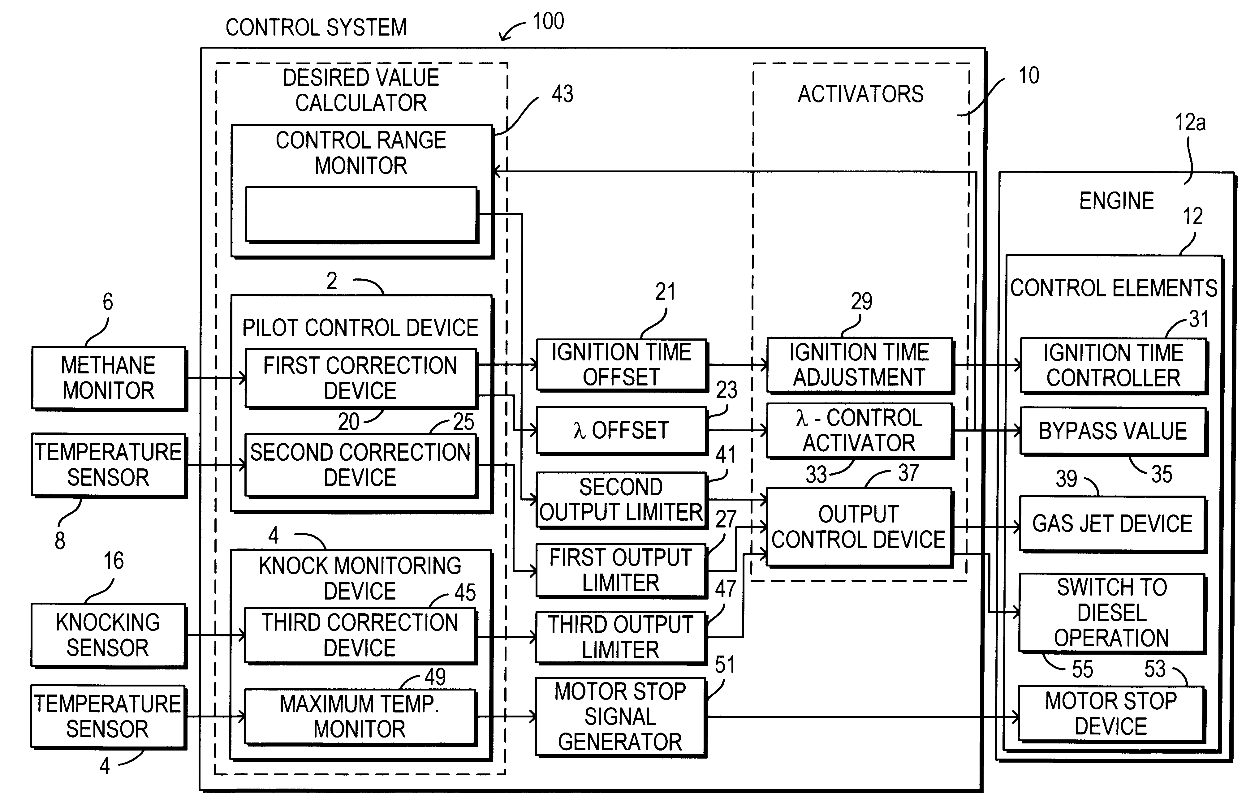
According to the preferred embodiment, a control system 100 for a diesel gas engine 12a is shown in FIG. 1 which comprises a pilot control device 2 and a knock monitoring device 4. The pilot control device 2 is connected to a methane monitor 6 which generates a signal corresponding to an amount of methane as an input to the pilot control device 2. In addition, the pilot control device 2 is also connected to a temperature sensor 8, which measures the charging air temperature and / or mixture temperature as an input signal of the pilot control device 2, depending on whether the engine 12a is supercharged.

As FIG. 1 shows, the pilot control device 2 comprises a first correction device 20 connected to the methane monitor 6 which outputs two methane amount correction signals. The first methane amount correction signal is transmitted to an ignition timing offset generator 21 which calculates a corresponding signal for the beginning of delivery or ignition timepoint offset as an output signal...


PUM


Abstract

A gas engine has a control system having a pilot control device for adjusting the operating state of the engine in response to changes in limiting conditions that are monitored. The control system further includes a knock monitoring device which is superordinate with respect to the pilot control device when the operating state reach a minimum distance from the knocking limit of the gas engine. The knock monitoring device prevents the engine from being damaged from circumstance which can not be protected against via the pilot control device.

Description

1. Field of the InventionThe invention relates a gas engine, especially a diesel gas engine, with a control system for controlling and regulating the gas engine in dependence on changing limiting conditions. More specifically, the invention relates to a gas engine with a pilot control device which receives measurements of the limiting conditions, calculates output signals, and transmits the output signals to activators which activate final control elements for adjusting the engine operating point to the changed limiting conditions.2. Description of the Related ArtModern gas engines that operate on the lean-burn principle are able to comply with the standards for NOx emissions (e.g., those based in Germany on T A Luft) without requiring exhaust gas after treatment, even at high mean pressures. One prerequisite for meeting the standards for NOx emissions is a lean gas-air mixture, which requires a high air-fuel ratio .lambda. in the combustion chamber (lean-burn method).The engine mus...

Claims


Application Information

Patent Timeline
Patent Type & Authority Patents(United States)
IPC IPC(8): F02D35/00F02D41/04F02D35/02F02D41/14F02P17/12F02D19/02F02D41/02F02D45/00F02M21/02F02P5/15
CPCF02D35/003F02D35/025F02D35/027F02D41/042F02D41/0027F02D41/1497Y02T10/36F02D2011/102F02D2200/0414F02D2200/0612Y02T10/30
Inventor RIECK, KAIGLAUBER, ROBERTLIERZ, KLAUSFELBER, THOMASDIER, LARS
Owner MAN B & W DIESEL AG
Learn More