Eureka AIR delivers breakthrough ideas for toughest innovation challenges, trusted by R&D personnel around the world.

Method for marking a gaming disk by pad printing

a technology of gaming disks and printing methods, applied in the direction of lithography, coins, rotary lithographic machines, etc., can solve the problems of incomplete marking, substantial modification of the side profile, incomplete marking, etc., and achieve the effect of improving the quality of the marking

Inactive Publication Date: 2001-01-23
GAMING PARTNERS INTERNATIONAL CORPORATION +1
View PDF7 Cites 33 Cited by
  • Summary
  • Abstract
  • Description
  • Claims
  • Application Information

AI Technical Summary

Benefits of technology

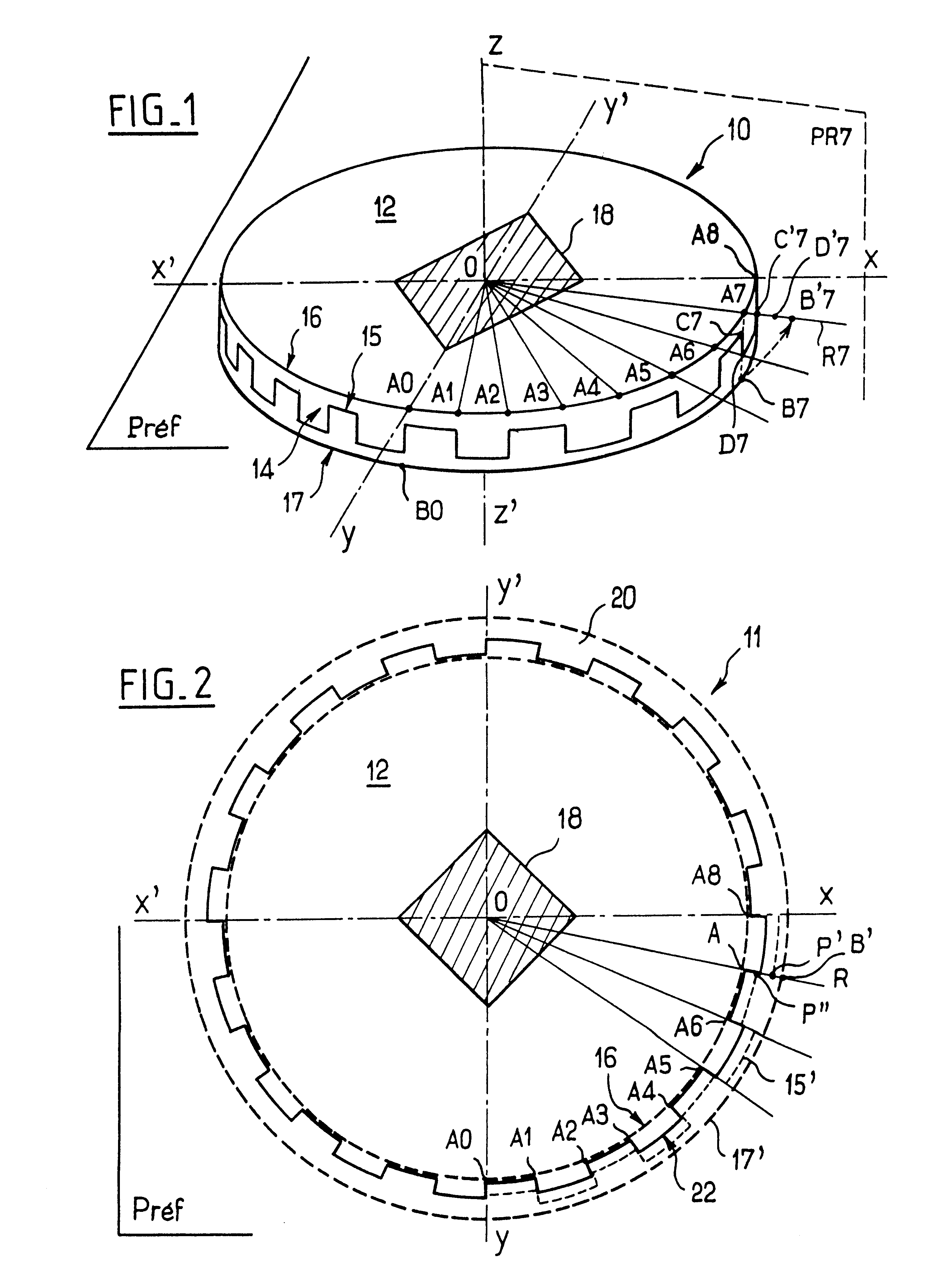
Thus, the use of the decoration image which is radially deformed with respect to the side decoration makes it possible to distribute the effect of distortion on the final decoration due to the variations in diameter of the chip over the entire circumferential perimeter of the side of the chip and to make this effect negligible.
Moreover, by making the internal circular border of the ring come into correspondence with the edge of the reference face of the chip, the heightwise positioning of the decoration is facilitated for marking a solid-straight-sided chip. Likewise, it is advantageous, in the radial contraction transformation, to use as relative origin on each radius OR the corresponding point A on the edge of the reference face of the chip.

Problems solved by technology

However, this technique, although satisfactory for the faces of the chip, is not always accepted by casinos for the side as it results in substantial modification of the profile of the side and / or in incomplete marking of the latter.
However, this technique, whose means of implementation are quite complex and expensive, is not always satisfactory, especially when the side decoration has to be reproduced with very great positional accuracy over the entire circular perimeter of the straight side (writing, bar code and various codings, periodic circular drawing).
In particular, since the principle of the rotating roller implies a point of origin on the side of the chip for the marking operation proper, this results in the formation of a "join" (either a blank or an overlap) in the decoration after marking the side over one complete revolution of the chip, the "join" being all the more difficult to avoid as the manufacturing tolerances of the chip cause slight, but quite real, variations in the diameter of the chips.

Method used


Image

  • Method for marking a gaming disk by pad printing
  • Method for marking a gaming disk by pad printing
  • Method for marking a gaming disk by pad printing

Examples


Embodiment Construction

It stems from the foregoing that there is a need for a new method of marking straight-sided gambling chips which eliminates, or appreciably reduces, the limitations and other drawbacks presented above.

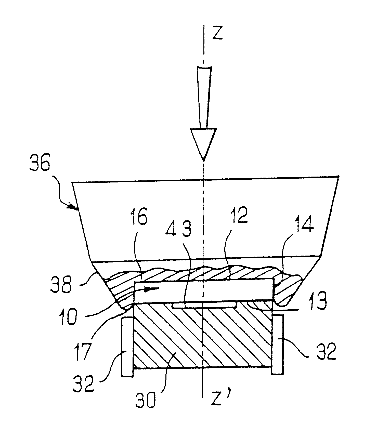
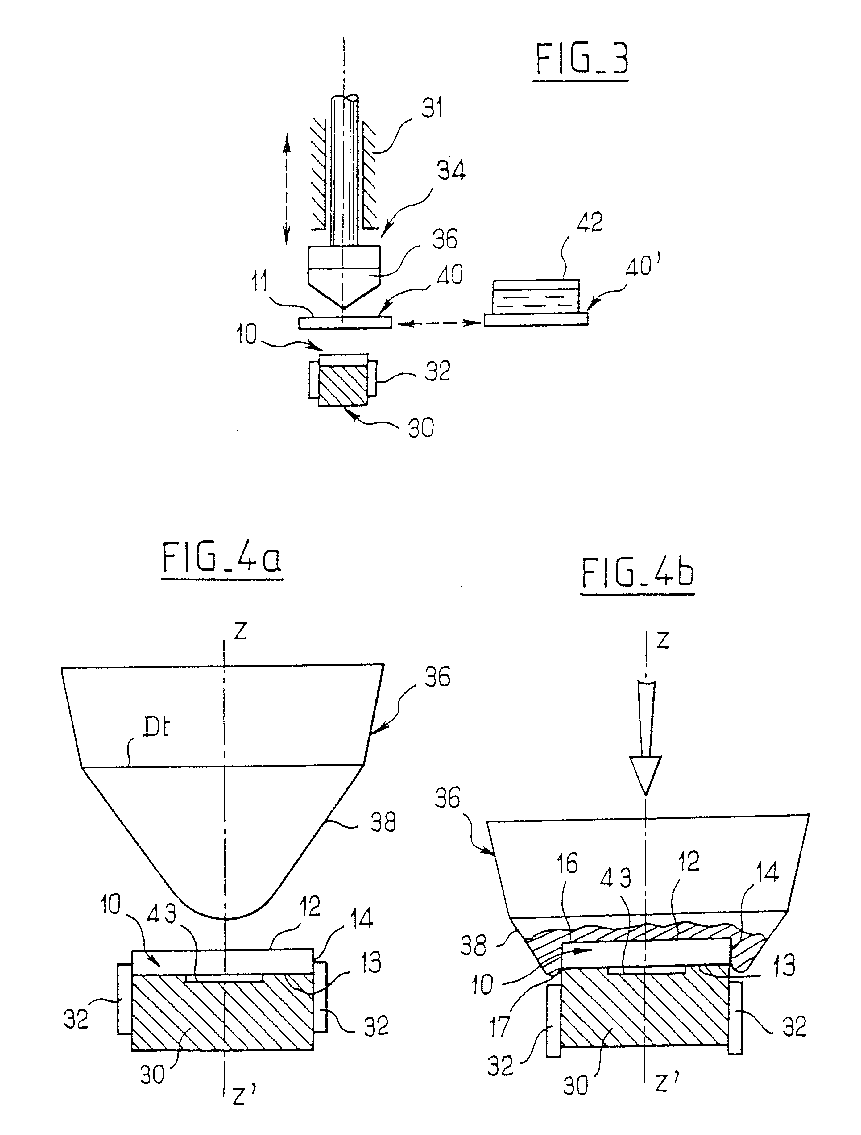
For this purpose, the invention provides a method of marking the side of a straight-sided disc-shaped gambling chip or an object of similar shape by pad printing, characterized by the use of an inked pad which is moved coaxially with the said chip in conjunction with a flat ink plate having a ring-shaped zone suitable for being placed coaxially with the pad and bearing a decoration image defined by a radially deformed representation of the decoration of the straight side of the chip.

Thus, the use of the decoration image which is radially deformed with respect to the side decoration makes it possible to distribute the effect of distortion on the final decoration due to the variations in diameter of the chip over the entire circumferential perimeter of the side of the chip and to make th...


PUM

PropertyMeasurementUnit
Fractionaaaaaaaaaa
Fractionaaaaaaaaaa
Diameteraaaaaaaaaa

Abstract

A method for marking a side of a straight-sided chip with a decoration by pad printing. The method comprises providing an ink plate with an image defined by radially deformed representation of the decoration of the straight side of the chip in a ring-shaped zone, moving a pad coaxially into contact with the ink plate such that the image transfers to the pad, and moving the pad coaxially into contact with the chip such that the image transfers to the side of the chip.

Description

This is a national stage application, under 35 USC .sctn.37, of international application No. PCT / FR98 / 00485, filed Mar. 11, 1998.The present invention relates to the marking of gambling chips having the general shape of a disc, or of objects of similar shape, by pad printing. Gambling chip, also called casino chip, should be understood to mean any element which can be used in gambling halls and represents a nominal value which may or may not be predetermined. Generally, these chips are manufactured from a rigid and scratch-resistant plastic.Gambling chips are, almost systematically, given a decoration by marking on their faces and / or sides, this decoration, depending on the eventual uses of the chips, possibly ranging from the simplest to the most complex. For the rest of the specification, the term decoration should be understood in its widest sense and it comprises, in particular, any drawing, symbol, mark and character (for example, letters, numbers, bar codes or various codings...

Claims


Application Information

Patent Timeline
IPC IPC(8): A44C21/00B41F17/00
CPCA44C21/00B41F17/001
Inventor CHARLIER, GERARDPHILIPPE, ERICTOLLHUPP, MICHEL
Owner GAMING PARTNERS INTERNATIONAL CORPORATION
Why Eureka
Eureka Blog
Learn More