
Process and device for atomizing liquid extinguishing agents in stationary extinguishing installations

a technology of extinguishing agent and stationary extinguishing device, which is applied in the direction of burners, medical science, combustion types, etc., can solve the problems of large water supply and machine output, disadvantages of extinguisher units for particular applications, and large damag

Inactive Publication Date: 2001-01-16
ALSTOM (SWITZERLAND) LTD +1
View PDF5 Cites 37 Cited by
  • Summary
  • Abstract
  • Description
  • Claims
  • Application Information

AI Technical Summary

Benefits of technology

An object of the present invention is to reduce, particularly in a stationary water spray extinguisher unit, the amount of liquid extinguishing medium, as commonly used in a conventional extinguisher units, needed to extinguish a fire.
It should be noted that a two-phase bubble flow is produced by the inventive process, in that more inert gas is added than can go into solution. This two-phase bubble flow in the tubular conduit system in a simple fashion produces at the nozzle an aerosol with optimal droplet size for fire fighting.
One advantage of the present invention is that the liquid inert gas largely dissolves in the liquid extinguishing medium under high pressure and is conveyed to the fire by means of the produced droplets, since a dynamic process of degasification takes longer than the transport time. This improves the extinguishing effect, because the droplets split again en route to the fire. Advantageously, the fire is better extinguished with the very fine water mist that is produced.
As a result of the formation of micro-droplets in the area of the fire, particularly due to the separation of the liquid extinguishing medium and the inert gas, the surface of the liquid extinguishing medium is considerably enlarged. In addition, the inert gas (e.g., CO.sub.2) absorbs radiated energy, and vaporization of the liquid extinguishing medium removes energy from the fire. In this way, energy surplus in an area of the fire is reduced so far that a high extinguishing effect, which could not be attained solely by the use of micro-droplets without the mixing in of preferably liquid inert gas, is attained.
It is preferable, however, to control the amount of the inert gas, in particular, the liquid inert gas, e.g., CO.sub.2, added in dependence on a concentration of the inert gas in the extinguishing area during the extinguishing, so that a maximum MAK value of 10,000 ppm or the maximum value usual in inergenic extinguisher units (<4% by volume) is not exceeded.

Problems solved by technology

These extinguisher units have disadvantages for particular applications.
This can lead to considerable damage.
Moreover, large supplies of water and machine outputs must be installed.
Foam extinguisher units entail increased technical expense, and this leads to high installation costs.
High costs for disposal are also incurred.
Gas extinguisher units, which work, for example, by lowering the oxygen concentration by means of inertization in the extinguishing area, require considerable safety expenditure, particularly in the case of CO.sub.2 extinguisher units, due to the danger to personnel.
Certain other extinguishing gases that were previously used, e.g., halon, can no longer be used due to legal restrictions.
Other extinguishing mediums, e.g., argon, are relatively expensive.

Method used


Image

  • Process and device for atomizing liquid extinguishing agents in stationary extinguishing installations
  • Process and device for atomizing liquid extinguishing agents in stationary extinguishing installations

Examples


Embodiment Construction

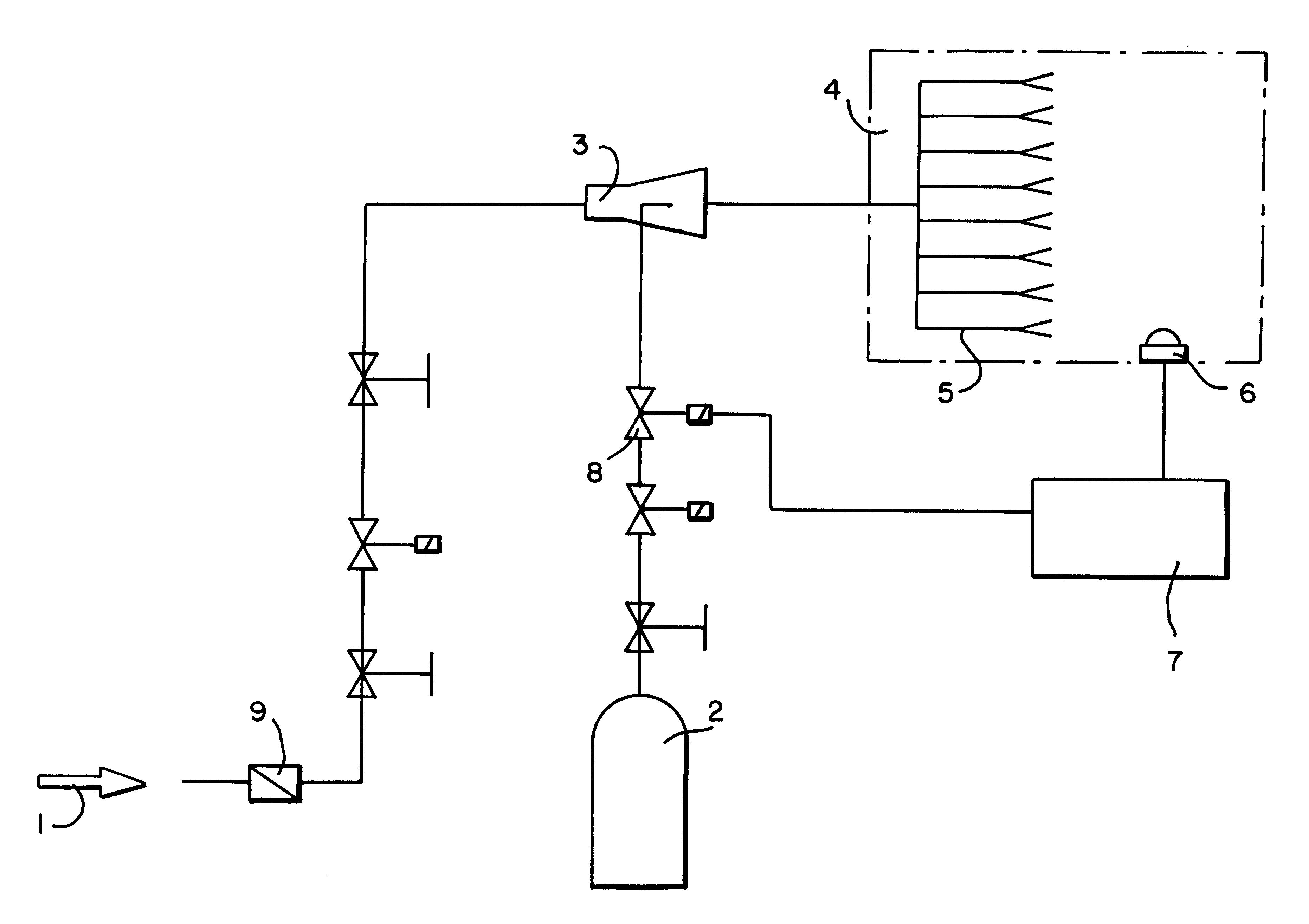
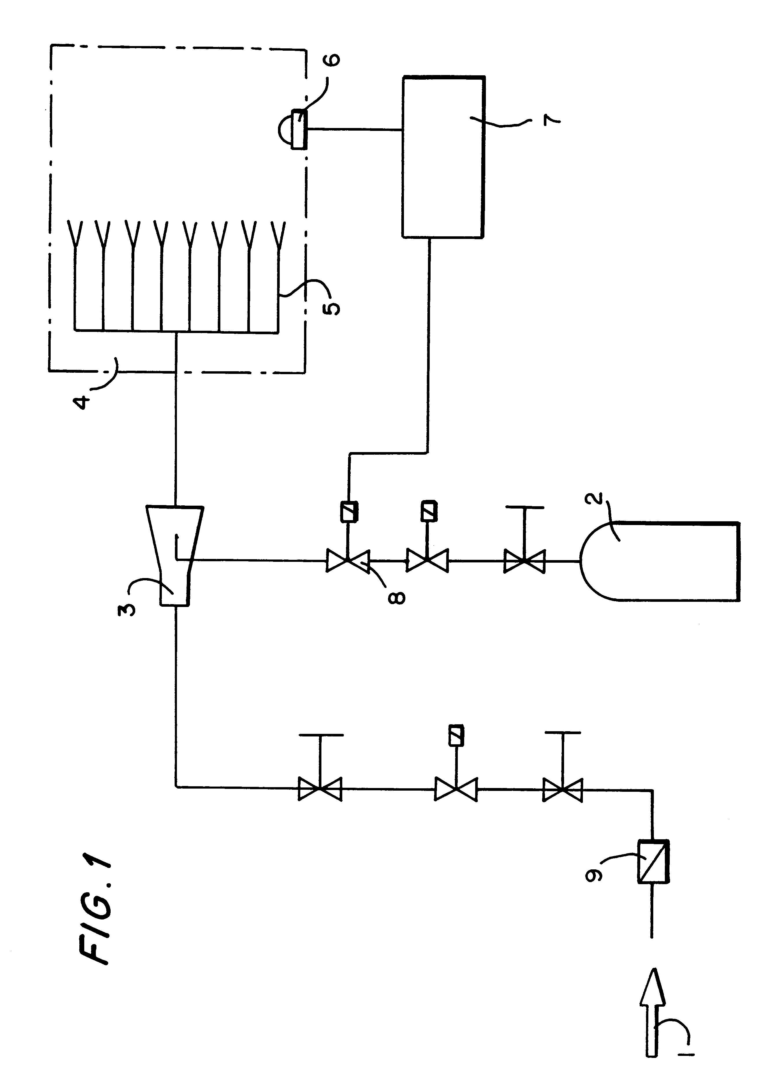
The device according to the invention has, along with the usual conduits and suitable blocking devices, a non-return valve (9) arranged at a liquid extinguishing medium supply, preferably water. In preferably mixing unit (3), the liquid extinguishing medium is mixed with a liquid inert gas flowing from a reservoir (2) to form a liquid extinguishing medium mixture. Between the reservoir (2) and the mixing unit (3) are arranged suitable blocking devices and a control valve (8) for controlling flow of the liquid inert gas.

The liquid extinguishing medium mixture is conveyed to a distributing device, such as nozzles (5), so as to produce an atomized spray for extinguishing a fire. An extinguishing area (4) is defined by the aerosol spray. A detector (6) is arranged within the extinguishing are (4) for measuring parameters related to extinguishing of the fire. The detector (6) is connected to an evaluation device (7) which in turn is connected to the control valve (8).

The blocking devices...


PUM


Abstract

A process and a device for atomization of a liquid extinguishing medium, in which the liquid extinguishing medium and a liquid inert gas are mixed in a mixing unit to form a liquid extinguishing medium mixture. The mixture is conveyed through a conduit to a distributing device such as extinguishing nozzles. As the mixture exits the distributing device the mixture is atomized, forming an aerosol spray for extinguishing a fire within an extinguishing area defined by the aerosol spray. A detector arranged in the extinguishing area for detection of parameters relating to extinguishing of the fire is connected to an evaluation device which in turn is connected to a control valve. The control valve regulates the quantity of liquid inert gas supplied to the mixing unit.

Description

1. Field of the InventionThe present invention relates to a process and a device for mixing liquid inert gas with a liquid extinguishing medium (e.g., water) and for subsequent atomization of the mixture for the purpose of fire fighting. The present invention is suitable for stationary, and mobile, fire extinguisher units.2. Description of the Related ArtUsually, sprinkler, foam, water spray and gas extinguisher units are used for extinguishing fires.These extinguisher units have disadvantages for particular applications. For example, a great deal of water is used in sprinkler and water spray extinguisher units. This can lead to considerable damage. Moreover, large supplies of water and machine outputs must be installed. Foam extinguisher units entail increased technical expense, and this leads to high installation costs. High costs for disposal are also incurred. Gas extinguisher units, which work, for example, by lowering the oxygen concentration by means of inertization in the ex...

Claims


Application Information

Patent Timeline
Patent Type & Authority Patents(United States)
IPC IPC(8): A62C39/00A62C35/02A62C5/02A62C99/00
CPCA62C99/0072A62C99/00
Inventor RUSSWURM, MANFREDAEBISCHER, FREDERIC
Owner ALSTOM (SWITZERLAND) LTD
Learn More