
Carrier for electronic parts

Inactive Publication Date: 2000-11-21
FUJITSU TAKAMIZAWA COMPONENT LTD +1
View PDF11 Cites 41 Cited by
  • Summary
  • Abstract
  • Description
  • Claims
  • Application Information

AI Technical Summary

Benefits of technology

It is, therefore, an object of the present invention to provide a carrier for electronic parts, which can improve the mechanical strength of the walls of storage sections without unnecessarily enhancing the entire stiffness of the carrier and, thus, can be effectively used for relatively large electronic parts.
It is further object of the present invention to provide a packed article with high reliability, the packed article including a plurality of electronic parts and a carrier for packing the electronic parts.

Problems solved by technology

In the above-described conventional carriers for electronic parts, a problem has been arisen in which the electronic parts are moved in the corresponding storage sections during carrying and storing, which results in a lead damage and / or a difficulty in smoothly taking out the electronic parts by the automatic mounting machine.
Accordingly, the relatively thinner plastic sheet material may result in the reduced thickness of the walls of the storage sections formed as recesses and thus in an insufficient mechanical strength thereof.
The deformation of the walls of the storage sections may cause the accommodated electronic parts, or particularly the leads thereof, to be damaged.
The problem of the insufficient mechanical strength of the walls of the storage sections may become significant when the dimension of the electronic part to be accommodated is increased.
However, it is not desirable to merely increase the thickness of the plastic sheet material in order to thicken the storage section walls, because the entire stiffness of the molded carrier tape would be unnecessarily enhanced and thereby the operability for rolling the carrier tape onto the reel would be deteriorated.
Accordingly, if the thickness of the plastic sheet material is merely increased in order to improve the strength of the storage section walls, the entire stiffness of the carrier would be unnecessarily enhanced, which causes a disadvantage that the cutter is worn away in a cutting process in a relatively short time.
This may be caused in the case of the tray and of the carrier tape.

Method used


Image

  • Carrier for electronic parts
  • Carrier for electronic parts
  • Carrier for electronic parts

Examples


first embodiment

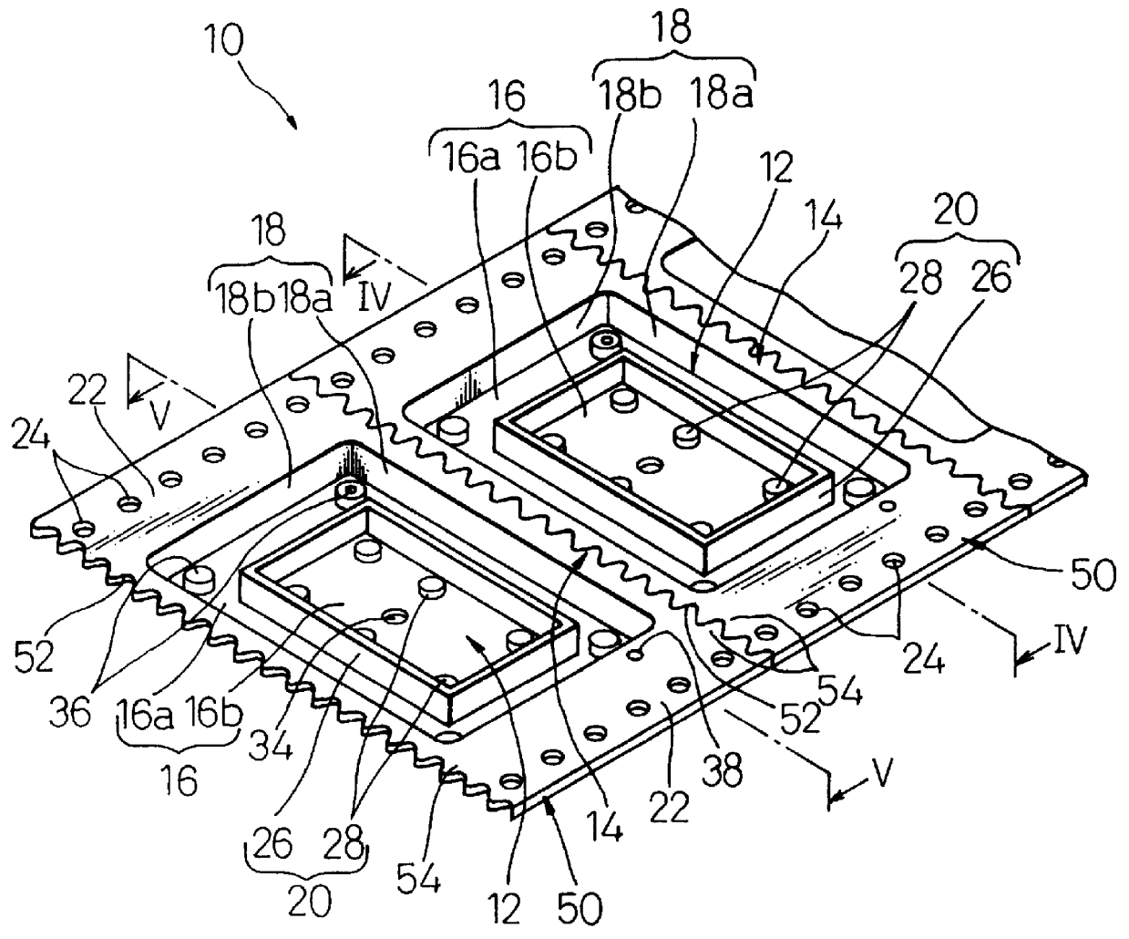
Referring now to the drawings, wherein the same or similar components are designated by the common reference numerals, FIG. 3 shows a part of a carrier 10, for electronic parts, according to the present invention; FIG. 4 shows one part of the carrier 10 and an electronic part P accommodated therein; and FIG. 5 shows another part of the carrier 10 and the electronic part P.

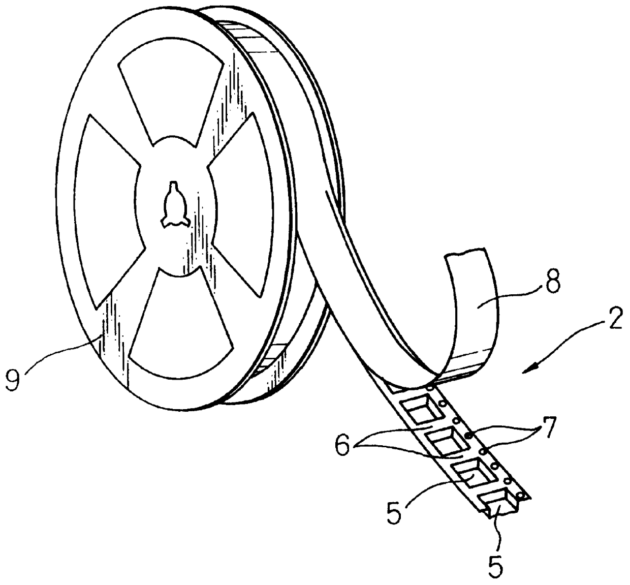
The carrier 10 includes a plurality of storage sections 12 defining recesses for individually accommodating electronic parts P and a plurality of connecting sections 14 for connecting the adjacent storage sections 12 with each other. The storage sections 12 are regularly arranged in a line with the connecting sections 14 being interposed therebetween, and thus the carrier 10 is constructed as a carrier tape.

Each of the storage sections 12 is provided with a bottom wall 16 and a side wall 18 for defining a recess having a generally rectangular shape in a plan view, and a support section 20 projecting from the bottom...

second embodiment

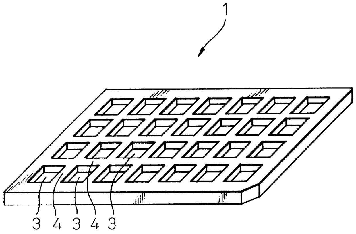
FIG. 10 shows a part of a carrier 60 for electronic parts, according to the present invention. The carrier 60 includes a plurality of storage sections 62 defining recesses for individually accommodating electronic parts and a plurality of connecting sections 64 for connecting the adjacent storage sections 62 with one another. The storage sections 62 are regularly arranged in a matrix with the connecting sections 64 being interposed therebetween, and thus the carrier 60 is constructed as a tray.

The structures of the storage sections 62 and the connecting sections 64 substantially conform to the structures of the storage sections 12 and the connecting sections 14 of the carrier 10 shown in FIG. 3, and thus are not repeatedly described in detail. It should be noted, however, that all of the storage sections 62 and the connecting sections 64 in the carrier 60 are integrally molded in a single mold through an injection molding process. Also, it will be easily appreciated in this structur...


PUM


Abstract

The carrier including a plurality of storage sections for individually accommodating electronic parts and a plurality of connecting sections for connecting the adjacent storage sections with each other. Each storage section is provided with a bottom wall and a side wall for defining a recess, and a support section for supporting the electronic part. The support section includes one rib continuously extending on the bottom wall along a generally rectangular profile, and a plurality of columnar projections projecting from the bottom wall to a height generally identical to one another and lower than a height of the rib. The bottom wall includes a first surface extending between the side wall and the rib to define a first region of the recess, and a second surface extending inside the rib to define a second region of the recess shallower than the first region. The columnar projections are arranged in a distributed manner on the second surface of the bottom wall. The bottom wall is locally thickened at portions corresponding to the rib and the columnar projections.

Description

BACKGROUND OF THE INVENTION1. Field of the InventionThe present invention relates to techniques for storage or handling of electronic parts and, more particularly, to a carrier used for carrying and storing surface-mount type electronic parts, such as surface-mount packages.2. Description of the Related ArtConventionally, for surface-mount electronic parts such as surface-mount IC or LSI packages, an electronic part provided with a molded body and a plurality of leads extending from the body is usually carried and stored in such a condition as to be accommodated in an exclusive container or carrier, to eliminate dust accumulation, lead damage, short circuits, and so on. The known structure of the carrier is, e.g., a tray (FIG. 1) or a carrier tape (FIG. 2).As shown in FIG. 1, the conventional tray 1 includes a plurality of storage sections 3 defining recesses for individually receiving electronic parts (not shown) in a regular arrangement as, e.g., a matrix. A manufacturer of electr...

Claims


Application Information

Patent Timeline
IPC IPC(8): H05K13/00B65D73/02B65D85/86
CPCH05K13/0084
Inventor TANAKA, KATSUHIKOANDO, YUKIOKANAZAWA, YUUKI
Owner FUJITSU TAKAMIZAWA COMPONENT LTD
Learn More