Interpenetration apparatus for meausurement of underground blasting vibration

Inactive Publication Date: 2000-05-16
HYUNDAI ENGINEERING AND CONSTRUCTION
View PDF3 Cites 16 Cited by
  • Summary
  • Abstract
  • Description
  • Claims
  • Application Information

AI Technical Summary

Benefits of technology

is to provide an interpenetration apparatus for the measurement of a magnitude of a blasting vibration for enabling a sensor to be interpenetrated thereunto to detect the blasting vibration transferred in radial directions closest to a blasting place, thereby enhancing the precision and reliability on the measurement of the blasting vibration.
Another object of the invention is to provide an interpenetration apparatus for the measurement of a magnitude of a blasting vibration for facilitating a sensor to be mounted therein or separated therefrom, thereby improving the working environment on the underground blasting vibration measurement.
Another object of the invention is to provide an interpenetration apparatus for the measurement of a magnitude of a blasting vibration for protecting a sensor from the blasting vibration and impact and prolonging its life.
According to the interpenetration apparatus, the housing includes the fixture and the mover divided into two, symmetrically, in a manner that if one end of the fixture has an area smaller than that of the mover on the same surface, other end of the fixture has larger area than that of the mover on the same surface. The housing receives sensors in its mover and is inserted into the working hole perforated adjacent to the blasting place to enable the sensor to access to the blasting position nearest thereto. Therefore, the sensor can detect an exact magnitude of the blasting vibration. At that time, the handle facilitates the housing to be inserted and mounted in the working hole with a traction means. Then, the traction means is pulled outside to slidably move the mover along a slant guide groove on the fixture positioned by the handle until clogging the working hole. It means that two lager diameter portions of the handle and the traction means are tightly secured to the inner surrounding wall portion of the working hole.

Problems solved by technology

Herein, it is noted that the conventional method fails to teach means or a method for mounting the sensor adjacent to the blasting place.
It has a problem in that an amount and magnitude of the blasting vibration can not be exactly measured.
Firstly, even through the sensor is mounted on the side wall of an approach to a tunnel by means of a tape or by using adhesive agents, but the sensor was used to be easily escaped from its mounting position due to the blasting vibration.
It results in making impossible to perform the measuring work of the underground blasting vibration.
Secondly, it was not possible for the sensor to detect an exact magnitude of the blasting vibration transferred to the underground from the blasting place, because it might be mounted at the position far away from the blasting place in order to prevent the escape that may occur upon the blasting.
Thirdly, it was anxious that the sensor is exposed directly to the blasting vibration and impact and may be broken down.
In order to overcome these problems, it has been limitedly practiced in some working places that the sensor is mounted into a flexible tube and the flexible tube is inserted into a hole perforated on the side wall of the tunnel approach in order to detect a magnitude of the blasting vibration.
It results in that the sensor could not react to the blasting vibration in a good sensitivity, thereby deteriorating the precision on the measurement of the blasting vibration.

Method used


Image

  • Interpenetration apparatus for meausurement of underground blasting vibration
  • Interpenetration apparatus for meausurement of underground blasting vibration
  • Interpenetration apparatus for meausurement of underground blasting vibration

Examples


Embodiment Construction

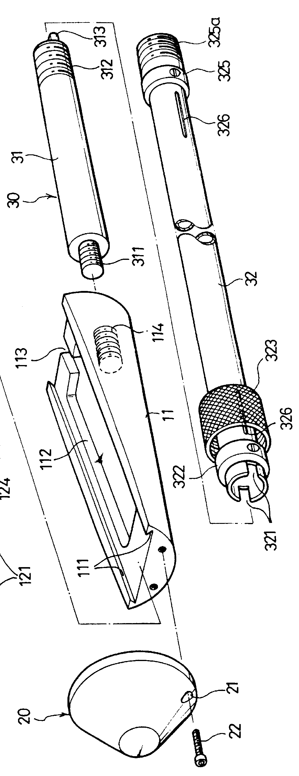
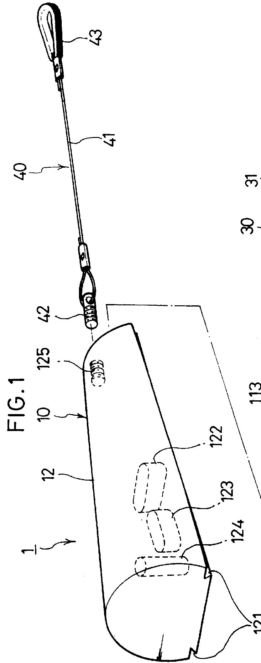
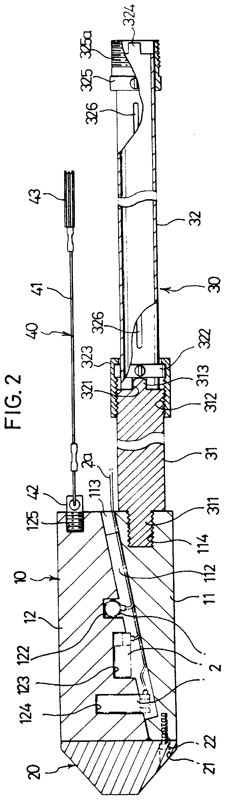
An interpenetration apparatus comprises a housing 10 divided into a fixture 11 and a mover 12, which are assembled into each other to form a cylinder and receive sensors 2 therein. The fixture 11 and the mover 12 are symmetrically cut in a longitudinal direction with respect to the housing 10 so that the chord length at one end surface of the fixture 11 is approximately equal to that at the other end surface of the mover 12. The fixture 11 includes slant guide grooves 111 longitudinally cut to be stepped at both ends thereof, a passage 113 formed at the end thereof to guide a cable into the housing 10 and a space 112 concaved in the bottom surface of the fixture 11 to receive the cable. The mover 12 includes a slant inserting embossment 121 stepped in a longitudinal direction to couple with the slant guide groove 111; and three receptacles 122, 123 and 124 respectively formed to receive sensors for detecting the blasting vibrations in X, Y and Z directions, respectively, wherein the...


PUM


Abstract

An interpenetration apparatus for the measurement of a magnitude of a blasting vibration comprises a housing including a fixture and a mover divided into two, symmetrically, in a longitudinal direction, in which the fixture includes a space for receiving a cable and the mover includes at least two grooves perforated to receive sensors, respectively; a head portion for fixing the front end of coupled fixture and mover to prevent the escape of the mover from the fixture; a handle including a fixing rod threadedly coupled to the rear portion of the fixture; a connecting rod connected to the fixing rod and extended in a predetermined length therefrom to insert the interpenetration apparatus into a working hole perforated adjacent to an approach to a tunnel; and a traction tool connected to the rear end of the mover to operate the mover, thereby enabling the housing to be at the nearest position from the blasting place, and sensitively detecting the wave motion of the blasting vibration as well as three dimensional blasting vibration transferred in all directions to the underground by the sensors to establish the accuracy measurement of the magnitudes of the blasting vibrations.

Description

The invention is related to providing a technology for measuring vibrations occurred upon the blasting of an underground tunnel construction, and particularly, to providing an interpenetration apparatus for the measurement of the underground blasting vibration, for sensing an magnitude of vibrations at the position nearest to a blasting place upon the blasting and measuring the magnitude of the blasting vibration in a higher accuracy.PRIOR ARTA conventional excavating method has been selectively performed by using an explosive charge in excavating a rock bed, effectively, during the constructing of a vertical or horizontal tunnel. It has required the measurement of a magnitude of blasting vibration transferred from the blasting place to the underground for determining the blasting method and position after recognizing the effects such as the disturbance of the surrounding underground.On the other hand, a conventional method comprises steps of mounting a sensor on the side wall of a ...

Claims


Application Information

Patent Timeline
IPC IPC(8): G01H1/12G01H1/00G01V1/18G01V1/16G10K11/00
CPCG01H1/12G10K11/004G01V1/184G01H1/00
Inventor SONG, MYUNG JUN
Owner HYUNDAI ENGINEERING AND CONSTRUCTION
Why Eureka
Try Eureka