
System and Method for Alignment of Volumetric and Surface Scan Images

Pending Publication Date: 2022-11-10
DGNCT LLC D B A DIAGNOCAT
View PDF0 Cites 2 Cited by
  • Summary
  • Abstract
  • Description
  • Claims
  • Application Information

AI Technical Summary

Benefits of technology

The patent text discusses an invention that aims to improve the accuracy and efficiency of medical diagnostics, specifically in dental and dental-related fields. The invention is an automated system and method that can align and segment volumetric and surface scan images, allowing dental professionals to more easily and accurately diagnose and treat dental conditions. The invention also addresses the limitations of existing image generation systems and techniques, such as CBCT and surface scans, by combining them to provide a more complete and accurate 3D representation of a patient. Overall, the invention aims to reduce the time and effort required for dental professionals to align and use the images in their practice.

Problems solved by technology

However, CBCT includes one or more limitations, such as time consumption and complexity for personnel to become fully acquainted with the imaging software and correctly using digital imaging and communications in medicine (DICOM) data.
Further, many dental professionals who incorporate this technology into their practices have not had the training required to interpret data on anatomic areas beyond the maxilla and the mandible.
To address the foregoing issues, deep learning has been applied to various medical imaging problems to interpret the generated images, but its use remains limited within the field of dental radiography.
Further, most applications only work with 2D X-ray images.
However, this method fails to be sufficiently robust for practical use.
However, the above references also fail to address the afore discussed problems regarding the cone beam computed tomography technology and image generation system.
The process of manual alignment is time-consuming.

Method used

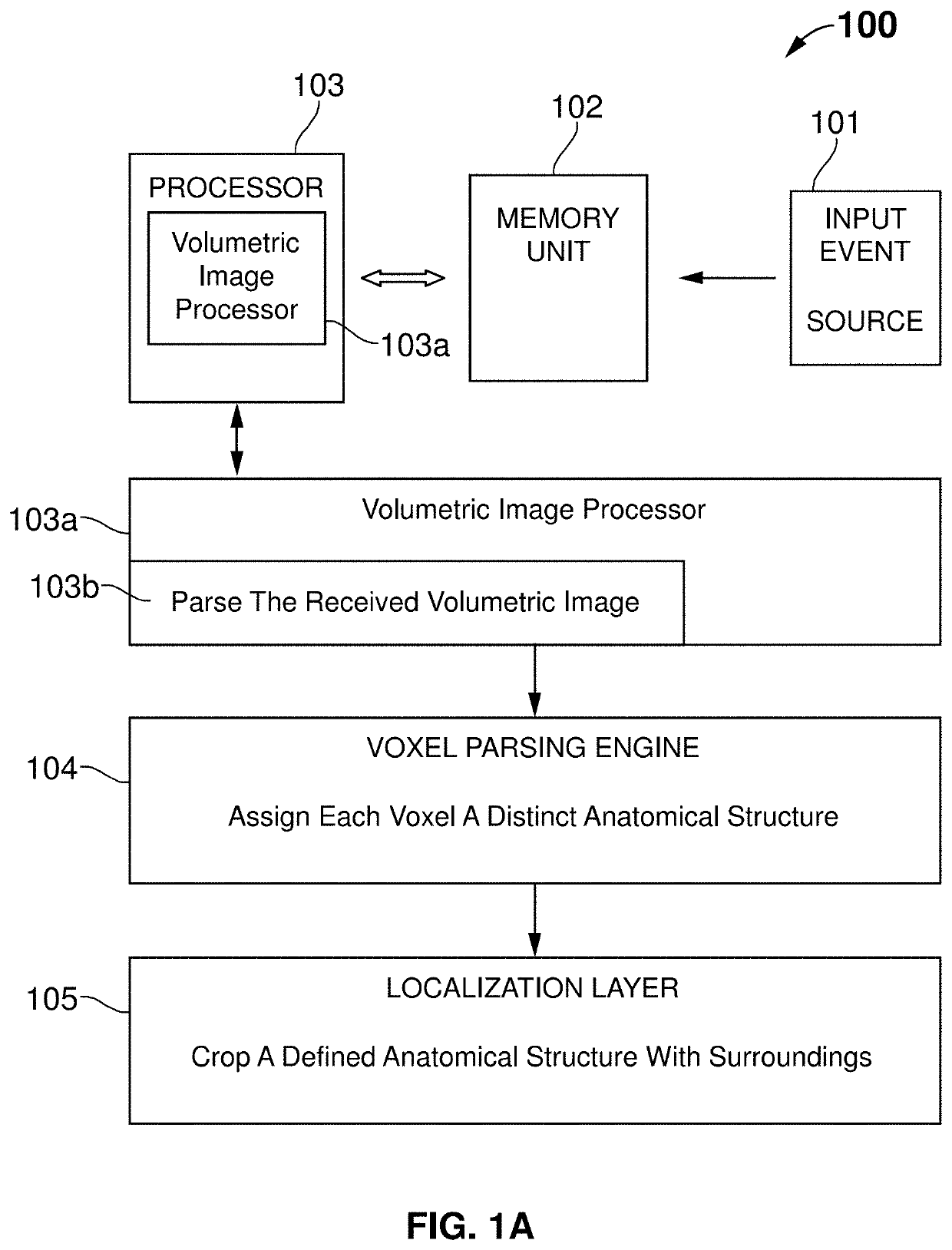
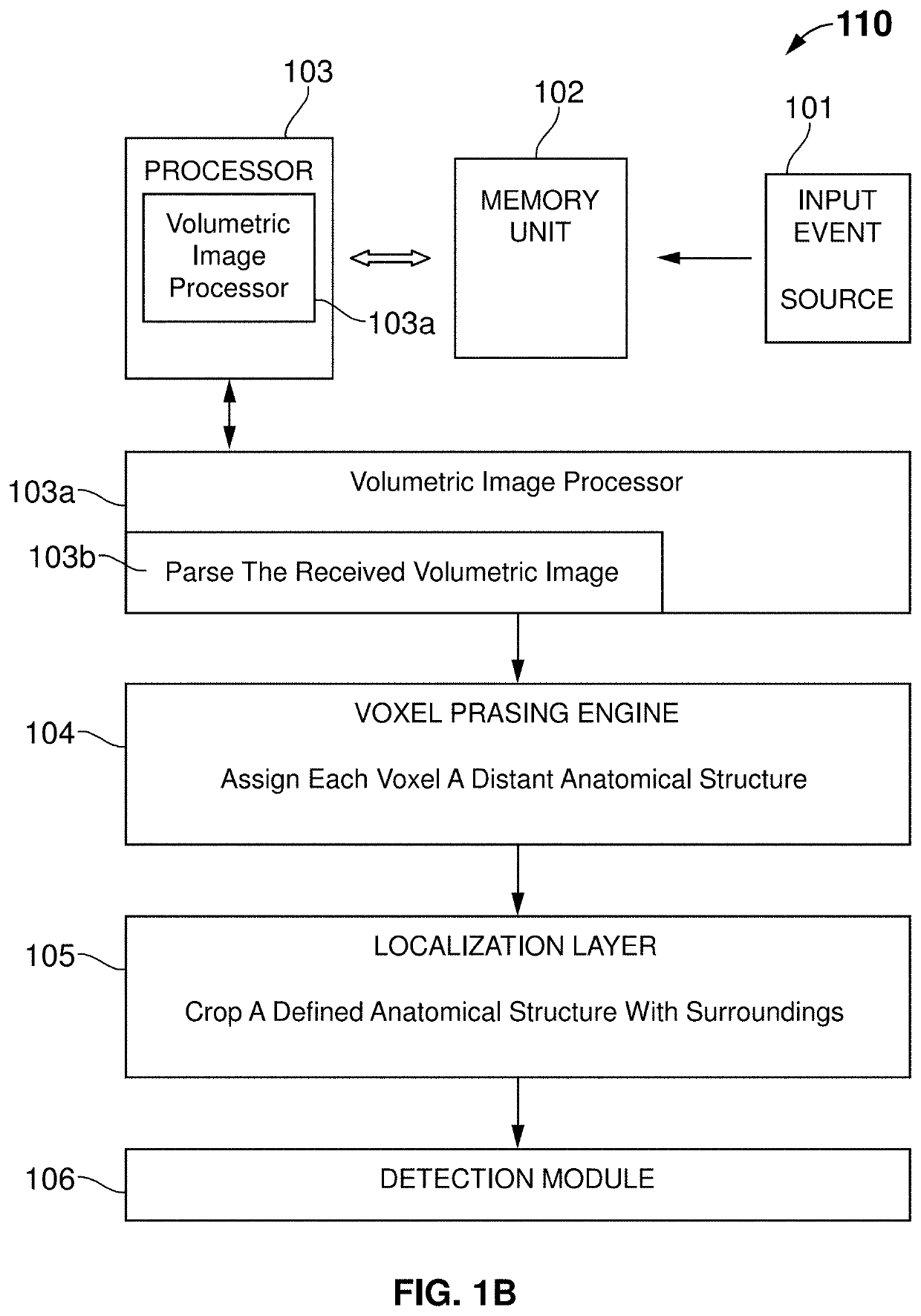
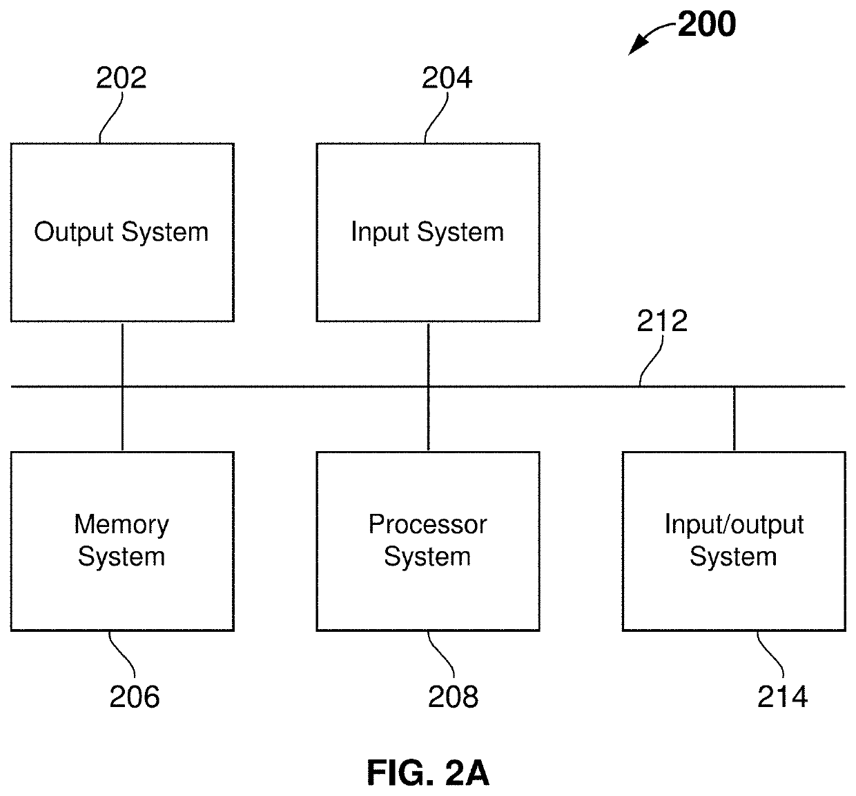

Image

  • System and Method for Alignment of Volumetric and Surface Scan Images
  • System and Method for Alignment of Volumetric and Surface Scan Images
  • System and Method for Alignment of Volumetric and Surface Scan Images

Examples


Embodiment Construction

[0039]In the following description, for purposes of explanation, numerous specific details are set forth in order to provide a thorough understanding of the invention. It will be apparent, however, to one skilled in the art that the invention can be practiced without these specific details.

[0040]Reference in this specification to “one embodiment” or “an embodiment” means that a particular feature, structure, or characteristic described in connection with the embodiment is included in at least one embodiment of the invention. The appearances of the phrase “in one embodiment” in various places in the specification are not necessarily all referring to the same embodiment, nor are separate or alternative embodiments mutually exclusive of other embodiments. Moreover, various features are described which may be exhibited by some embodiments and not by others. Similarly, various requirements are described which may be requirements for some embodiments, but not other embodiments.

[0041]The p...


PUM


Abstract

A method for alignment of volumetric and surface scan images, said method comprising the steps of: receiving a volumetric image and surface scan image, wherein the volumetric image is a three-dimensional voxel array of a maxillofacial anatomy of a patient and the surface scan image is a polygonal mesh corresponding to the maxillofacial anatomy of the same patient; segmenting the volumetric image and surface scan image into a set of distinct anatomical structures by assigning each voxel in the volumetric image an identifier by structure and assigning each vertex or face of the mesh from the surface scan image an identifier by structure, wherein at least one of the distinct anatomical structures are in common between the volumetric and the surface scan image; extracting a polygonal mesh from the volumetric image featuring common structures with the polygonal mesh from the surface scan image; converting both meshes from the volumetric image and from the surface scan to a point cloud; and aligning the converted meshes via point clouds using a point set registration.

Description

BACKGROUNDField[0001]This invention relates generally to medical diagnostics, and more specifically to an automated system and method for the alignment of volumetric and surface scan images for improving medical / dental diagnostics.Related Art[0002]Modern image generation systems play an important role in disease detection and treatment planning. Few existing systems and methods were discussed as follows. One common method utilized is dental radiography, which provides dental radiographic images that enable the dental professional to identify many conditions that may otherwise go undetected and to see conditions that cannot be identified clinically. Another technology is cone beam computed tomography (CBCT) that allows to the view of structures in the oral-maxillofacial complex in three dimensions. Hence, cone beam computed tomography technology is most desired over dental radiography.[0003]However, CBCT includes one or more limitations, such as time consumption and complexity for pe...

Claims


Application Information

Patent Timeline
Patent Type & Authority Applications(United States)
IPC IPC(8): G06T19/20G06T15/08
CPCG06T19/20G06T15/08G06T2210/12G06T2210/41G06T2207/20076G06T2207/30036G06T2207/10081G06T2207/20084G06T2207/10028G06T7/344G06T2210/56G06T17/20
Inventor EZHOV, MATVEYSANDERS, ALEXGOLITSYNA, MARIASHAMSHIEV, MAMAT
Owner DGNCT LLC D B A DIAGNOCAT
Learn More