Eureka AIR delivers breakthrough ideas for toughest innovation challenges, trusted by R&D personnel around the world.

Temperature-driven valve assembly

a technology of temperature-driven valves and components, which is applied in the direction of shock absorbers, springs/dampers design characteristics, vibration dampers, etc., can solve the problems of excessive force to close the load, be damaged, and become harder for the user or a motorised drive to close the load

Pending Publication Date: 2022-11-03
STABILUS
View PDF0 Cites 1 Cited by
  • Summary
  • Abstract
  • Description
  • Claims
  • Application Information

AI Technical Summary

Benefits of technology

The patent is about a valve that controls the temperature of a gas pressure spring, which helps to make it safer and more reliable. The valve is easy to make and use, which makes it an efficient solution for improving the performance of gas pressure springs.

Problems solved by technology

Consequently, it will become harder for the user or a motorised drive to close the load again against the force of the gas pressure spring.
Also, the high variability of the force with temperature as such poses a problem to the user since he / she may, for example, become accustomed to the large force to be applied by him / her at high temperatures (e.g., in the summer months) and will then, at a considerably lower temperature, apply excessive force to close the load whereby the load might, under certain circumstances, be damaged.
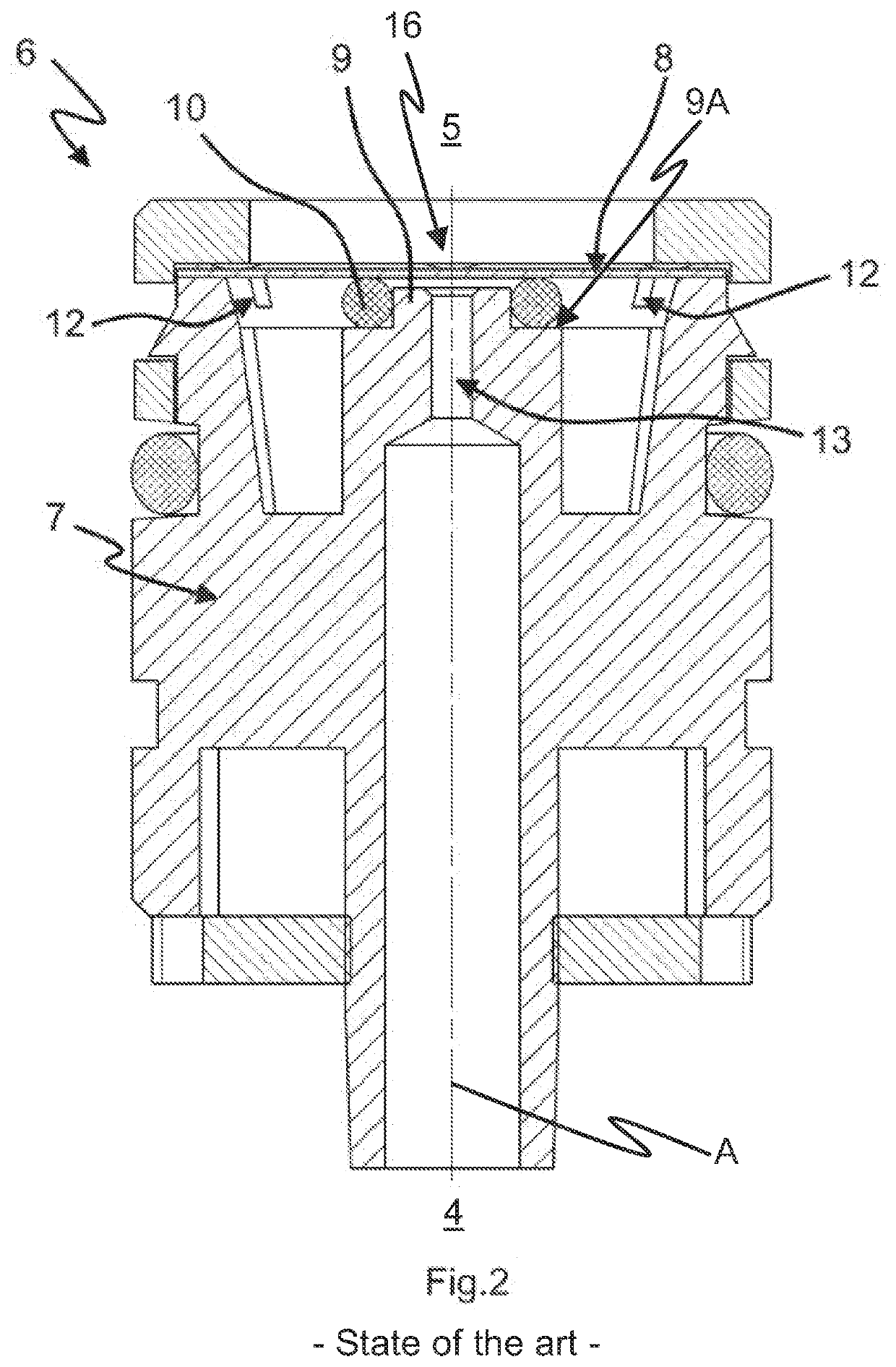
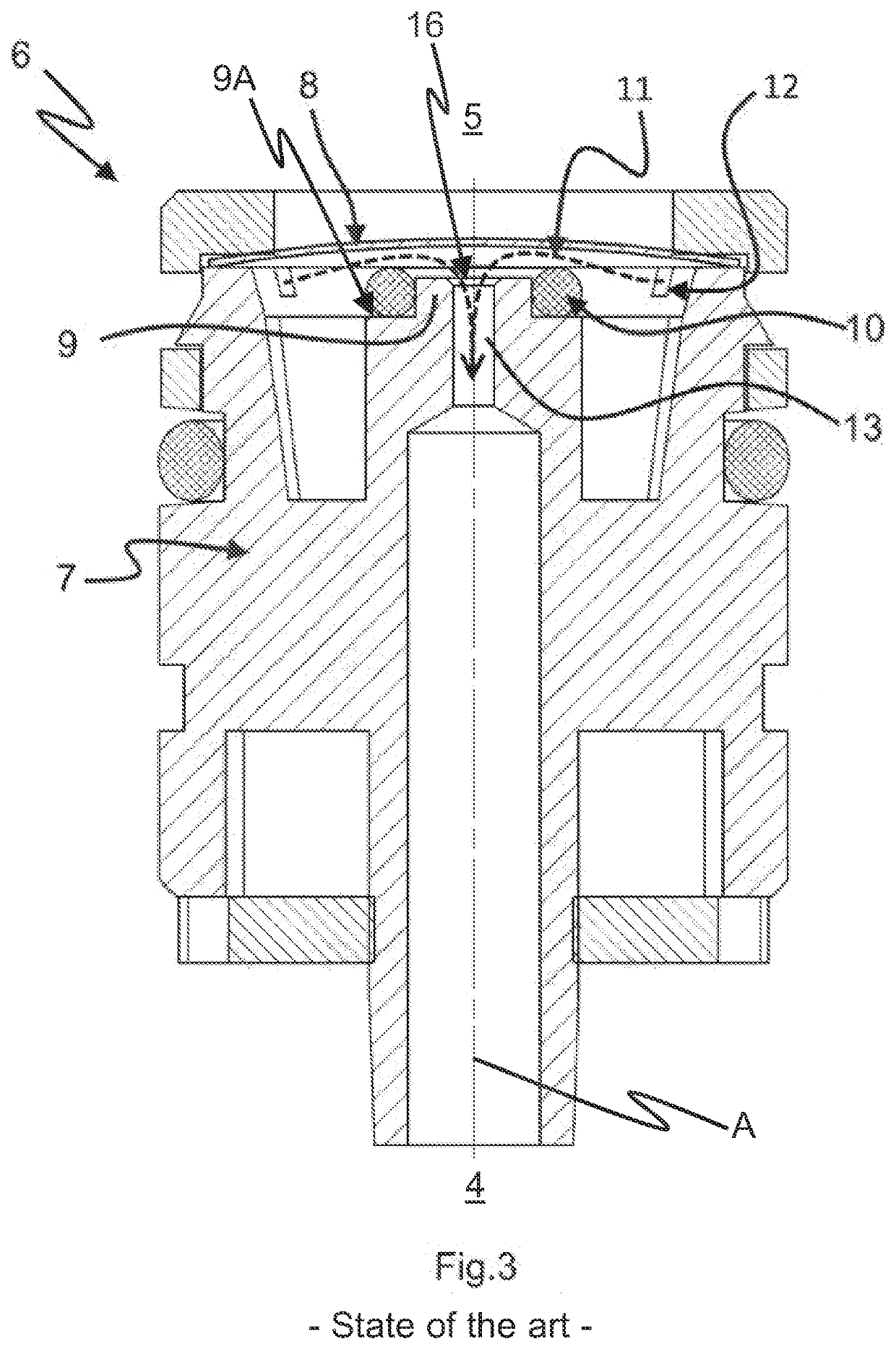
In tests on known gas pressure springs, an entrainment of the O-ring from its intended position by the bimetal spring is, in most cases, the cause of a non-opening of the known temperature-driven valve assemblies at low temperatures.
However, a positive fixation of the sealing means on the channel wall is expensive to produce.
Adhesively bonding the sealing means likewise increases production expenditure and is, in long-term use, particularly in case of frequent and large temperature fluctuations as encountered in case of a gas pressure spring used in a vehicle, not sufficiently reliable.

Method used


Image

  • Temperature-driven valve assembly
  • Temperature-driven valve assembly
  • Temperature-driven valve assembly

Examples


Embodiment Construction

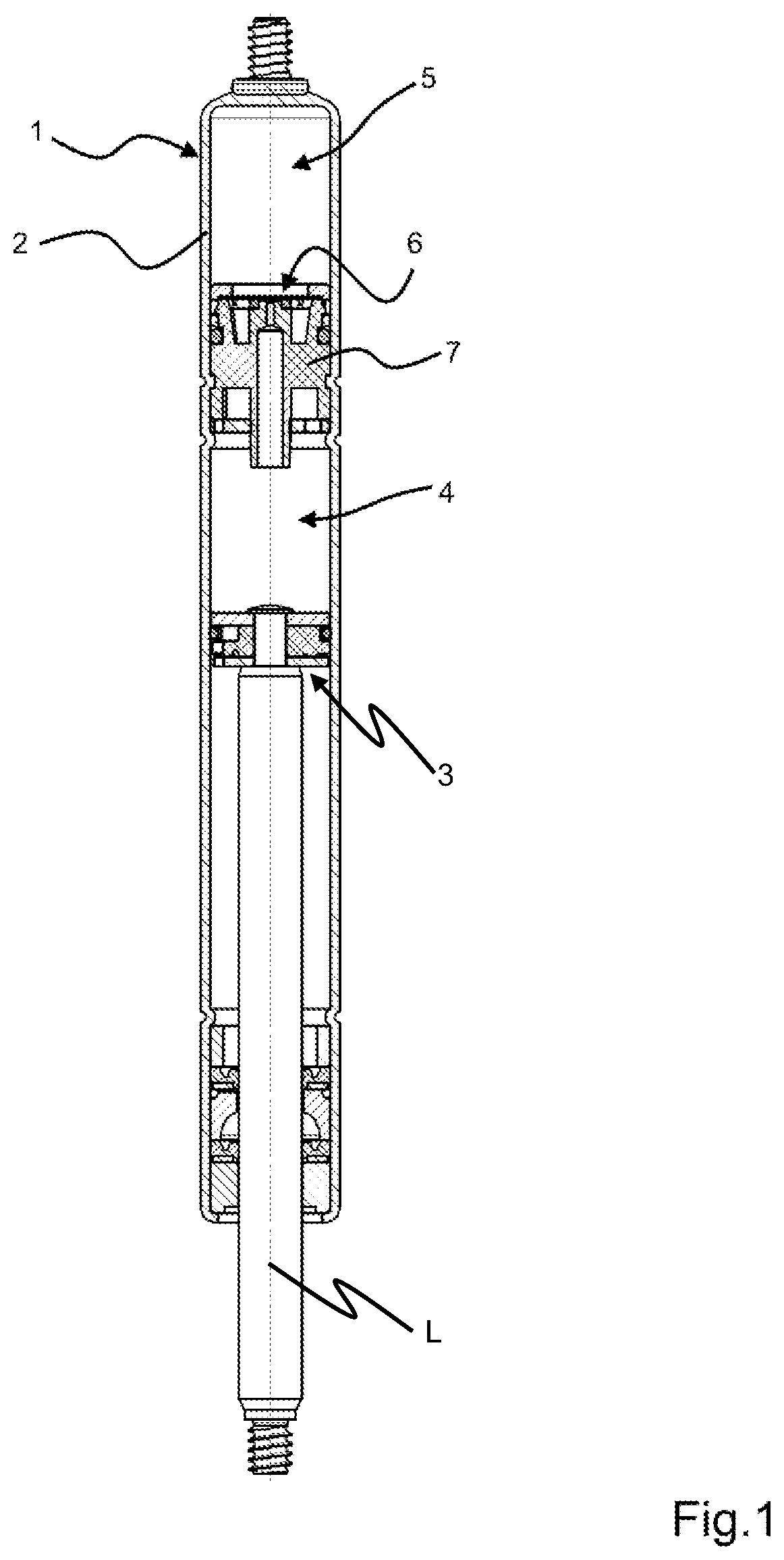
[0052]FIG. 1 shows an embodiment of a gas pressure spring 1 according to embodiments of the invention in the longitudinal cross-section along a longitudinal axis L of the gas pressure spring. The gas pressure spring comprises a housing 2 and a piston 3 slidable in the housing 2 along the longitudinal axis L of the gas pressure spring 1. The gas pressure spring 1 further comprises two chambers 4, 5 as well as a temperature-driven valve assembly 6 including a valve body 7. Depending on the temperature of the temperature-driven valve assembly 6, it does or does not establish a fluid-conducting connection between a main chamber 4 and a secondary chamber 5.

[0053]In a closing temperature range, for example at temperatures above 4° C., the valve assembly is closed, and the gas pressure spring 1 operates using only the main chamber 4. The gas pressure spring 1 will then offer a force delivery based on the gas mass and the gas volume contained in the main chamber 4.

[0054]In an opening temper...


PUM


Abstract

Provided is a temperature-driven valve assembly which can be manufactured in a cost-effective and simple manner as well as a gas pressure spring including the valve assembly which enables more reliable and safer operation of the gas pressure spring.

Description

CROSS-REFERENCE TO RELATED APPLICATIONS[0001]This application claims priority to PCT Application No. PCT / EP2020 / 066746, having a filing date of Jun. 17, 2020, based on German Application No. 10 2019 118 211.5, having a filing date of Jul. 5, 2019, the entire contents both of which are hereby incorporated by reference.FIELD OF TECHNOLOGY[0002]The following relates to a temperature-driven valve assembly comprising a channel portion for the fluid-conducting connection of two chambers for accommodating a fluid having a through opening for the fluid, at least one switching element having an opening configuration in an opening temperature range and a closing configuration in a closing temperature range, the switching element being, at least in sections, movable relative to the channel portion along an axis of movement in a temperature-driven manner, an opening normal of the through opening being oriented towards the switching element, and the channel portion being circumferentially enclos...

Claims


Application Information

Patent Timeline
IPC IPC(8): F16F9/52F16F9/02F16F9/36
CPCF16F9/523F16F9/0218F16F9/369F16F2230/24
Inventor BURRELL, JOSHUAFUHRMANN, CASTORSEIBERT, KARL-JOSEF
Owner STABILUS
Why Eureka
Eureka Blog
Learn More