
Nozzle for cleaner

a technology for cleaning nozzles and cleaners, which is applied in the direction of vacuum cleaners, carpet cleaners, floor cleaners, etc., can solve the problems of complicated structure of suction channels, inability to rotate all rotors, and long suction channels

Pending Publication Date: 2022-10-13
LG ELECTRONICS INC
View PDF0 Cites 0 Cited by
  • Summary
  • Abstract
  • Description
  • Claims
  • Application Information

AI Technical Summary

Problems solved by technology

However, according to prior art document 1, since a pair of rotors disposed at the left and right sides is rotated by one rotary motor, when the rotary motor breaks down or malfunctions, all of the pair of rotors cannot be rotated.
Accordingly, there is a defect that the suction channel is made long and the structure for forming the suction channel is complicated.
Further, since the water spray nozzle is disposed at the center of the cleaner body, while the dust cloth is arranged in the left-right direction, there is a problem that the dust cloth cannot sufficiently absorb the water sprayed ahead of the cleaner body.
Further, since there is no channel for suctioning air in prior art document 2, a floor can only be wiped, so a user has to manually remove dirt on the floor.

Method used


Image

  • Nozzle for cleaner
  • Nozzle for cleaner
  • Nozzle for cleaner

Examples


Embodiment Construction

[0089]Hereinafter, embodiments of the present invention are described in detail with reference to the exemplary drawings. It should be noted that when components are given reference numerals in the drawings, the same components are given the same reference numerals even if they are shown in different drawings. Further, in the following description of embodiments of the present invention, when detailed description of well-known configurations or functions is determined as interfering with understanding of the embodiments of the present invention, they are not described in detail.

[0090]Terms ‘first’, ‘second’, ‘A’, ‘(a)’, and ‘(b)’ can be used in the following description of the components of the embodiments of the present invention. The terms are provided only for discriminating the components from other components and, the essence, sequence, or order of the components are not limited by the terms. When a component is described as being “connected”, “combined”, or “coupled” with anot...


PUM


Abstract

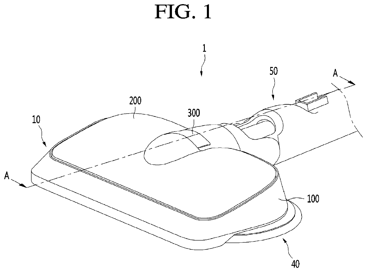
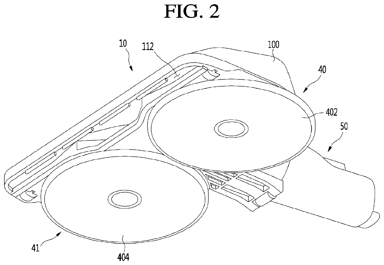
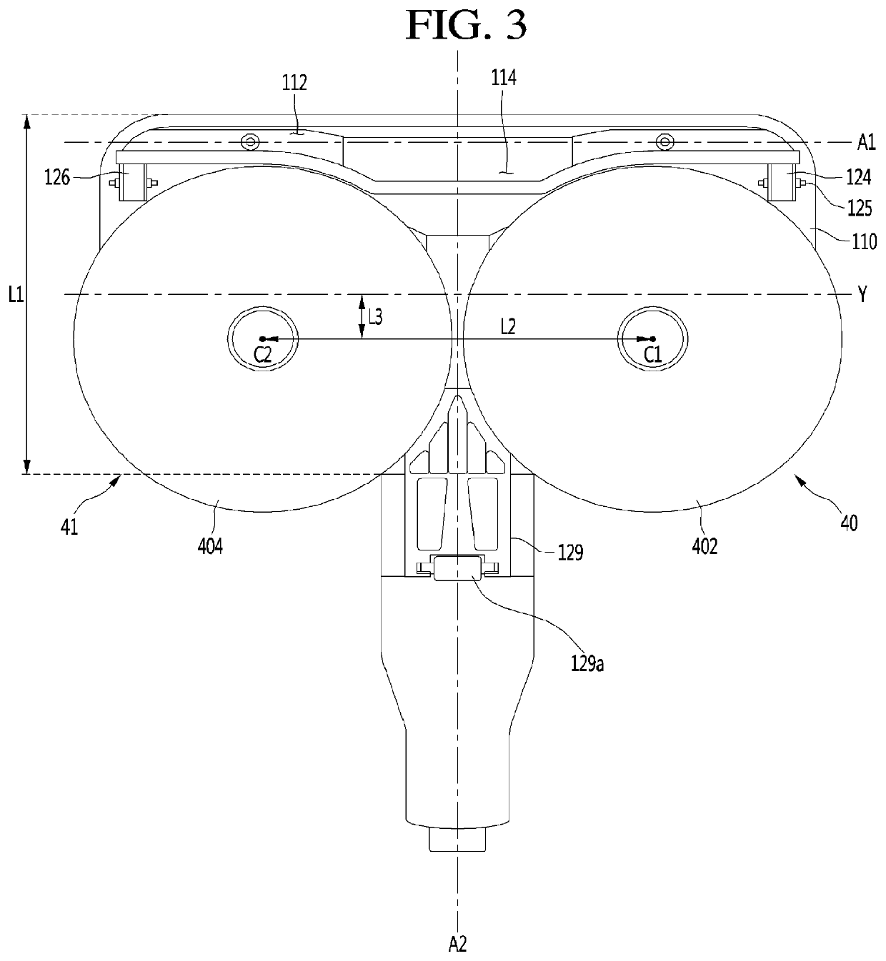
A nozzle for a cleaner has a nozzle main body including an intake channel to suction air. The nozzle includes first and second rotary cleaning units spaced apart from each other in a lateral direction under the nozzle main body. Each of the first and second rotary cleaning units includes a rotary plate coupled to a dust cloth. The nozzle further includes a first driving device to drive the first rotary cleaning unit and a second driving device to drive the second rotary cleaning unit. The nozzle includes a water tank to store water. Further, the nozzle has a water supply channel to supply water in the water tank to the rotary cleaning units. The nozzle has a water pump and a pump motor to drive the water pump to pump the water to the dust cloth.

Description

CROSS-REFERENCE TO RELATED APPLICATIONS[0001]This application is a continuation of U.S. application Ser. No. 16 / 398,582, filed Apr. 30, 2019, which claims priority under 35 U.S.C. § 119 to Korean Patent Application No. 10-2018-0050108, filed in the Republic of Korea on Apr. 30, 2018, and Korean Patent Application No. 10-2018-0088783, filed in the Republic of Korea on Jul. 30, 2018, the disclosures of all of which are hereby incorporated by reference in their entireties.BACKGROUND OF THE INVENTION[0002]The present invention relates to a nozzle for a cleaner.[0003]A cleaner is a device that performs cleaning by suctioning or wiping dust or dirt off of a place to be cleaned.[0004]Cleaners may be classified into a manual cleaner that a user moves in person for cleaning and an automatic cleaner that automatically moves for cleaning.[0005]Further, manual cleaners can fall into, depending on the types of cleaners, a canister cleaner, an upright cleaner, a handy cleaner, a stick cleaner, et...

Claims


Application Information

Patent Timeline
Patent Type & Authority Applications(United States)
IPC IPC(8): A47L11/206A47L11/40A47L9/06
CPCA47L11/206A47L11/4013A47L11/4094A47L11/4083A47L11/4038A47L9/068A47L11/201A47L11/2025A47L11/4069A47L11/408A47L11/4088A47L7/0009A47L9/0472A47L9/0686
Inventor RYU, JUNGWANKO, MOOHYUNSHIN, JINHYOUKYANG, INGYU
Owner LG ELECTRONICS INC
Learn More