
Display panel and display device

a display panel and display technology, applied in non-linear optics, instruments, optics, etc., can solve the problems of low light transmittance, poor viewing angle, and low aperture ratio of pixels

Active Publication Date: 2022-10-06
TCL CHINA STAR OPTOELECTRONICS TECH CO LTD
View PDF0 Cites 0 Cited by
  • Summary
  • Abstract
  • Description
  • Claims
  • Application Information

AI Technical Summary

Benefits of technology

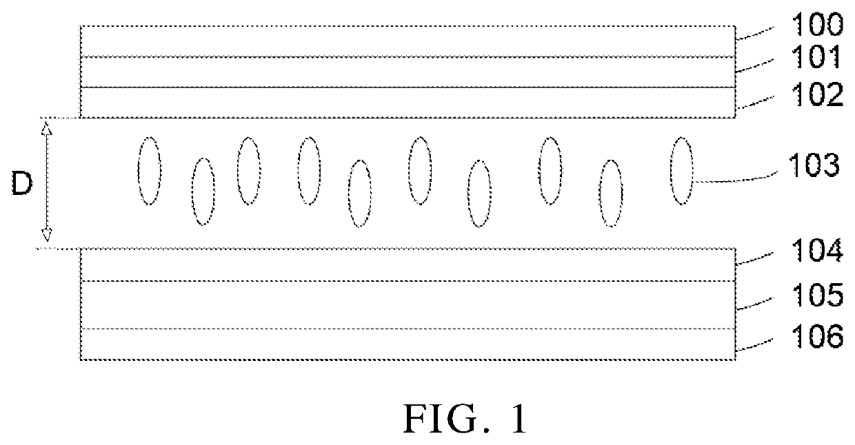
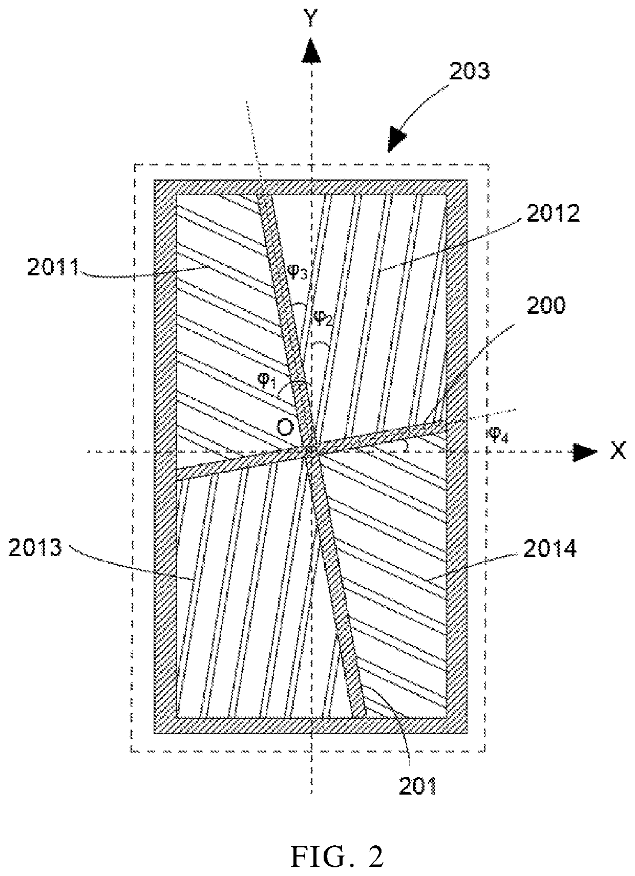
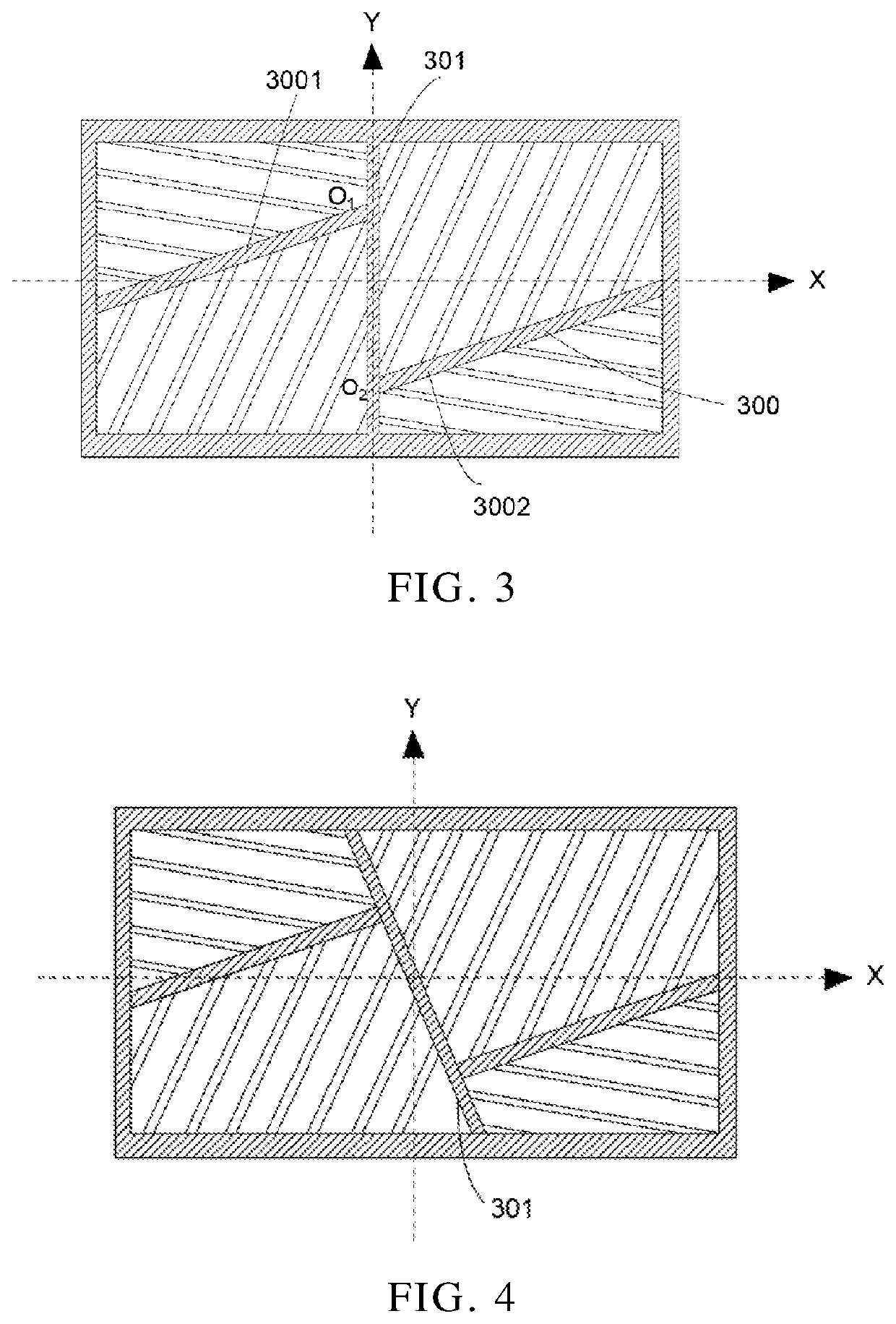
The present disclosure provides a display panel and display device with improved viewing angles and display quality. The panel has pixel electrodes with at least one stem electrode in each subpixel area, creating four liquid crystal domains. Each subpixel includes a primary subpixel and multiple second subpixels separated by a spacing. Different voltages applied to the primary and second subpixels provide three types of inversion of liquid crystal molecules, resulting in more liquid crystal domain regions without increasing the number of thin-film transistors. This increases light transmittance, improves viewing angles, and enhances display quality.

Problems solved by technology

But, under a pixel structure created by such a manner, there will inevitably be a certain area around pixels failing to operate normally and tending to form dark stripe areas, thereby adversely affecting display performance.
Furthermore, in current multi-domain pixel structures, in order to increase number of domains of pixel structures, pixels are forced to have low aperture ratios, low light transmittance, and poor viewing angles.
Furthermore, there is a problem, such as low aperture ratios of pixels, low light transmittance, and pool viewing angles, with multi-domain pixel structures.

Method used


Image

  • Display panel and display device
  • Display panel and display device
  • Display panel and display device

Examples


Embodiment Construction

[0040]The following embodiments are referring to the accompanying drawings for exemplifying specific implementable embodiments of the present invention.

[0041]With development of display technology, performance requirements of liquid crystal displays are getting higher and higher. Current liquid crystal display devices still have problems such as serious color shift at large viewing angles and relatively poor viewing angles, especially in display devices with a multi-domain design structure. With an increase in number of thin-film transistors, the loss of aperture ratios of display panels is serious, penetration rates of light are reduced, and finally display quality of panels is reduced, thereby adversely affecting improvement of comprehensive performance of the display panels.

[0042]An embodiment of the present disclosure provides a display panel. The display panel can obtain more liquid crystal domain regions while keeping number of existing thin-film transistors unchanged, thereby...


PUM

PropertyMeasurementUnit
angleaaaaaaaaaa
angleaaaaaaaaaa
angleaaaaaaaaaa

Abstract

A display panel and a display device are disclosed. The display panel includes upper and lower substrates, a liquid crystal layer, a first electrode, and a second electrode. The second electrode includes at least a stem electrode and a plurality of branch electrodes. A plurality of subpixel areas are provided, and each of the subpixel areas is divided into at least four liquid crystal domains by the stem electrode. The subpixel area in corresponding one of the liquid crystal domains is further divided to form a partition-like structure to increase number of liquid crystal domains, so that light transmittance and display quality can be improved.

Description

BACKGROUND OF INVENTION 1.FIELD OF INVENTION[0001]The present invention relates to a technical field of displays, and particularly to, a display panel and a display device.[0002]2. RELATED ART[0003]Liquid crystal displays (LCDs) have been widely used due to advantages of being compact, power saving, no radiation, etc.[0004]Currently, polymer stabilized vertical alignment (PSVA) technology is commonly used in a vertical alignment mode of liquid crystal displays, which has advantages of high contrast and quick response times. However, in the current PSVA technology, it is necessary to use ultraviolet irradiation in cell-assembly processes. But, under a pixel structure created by such a manner, there will inevitably be a certain area around pixels failing to operate normally and tending to form dark stripe areas, thereby adversely affecting display performance. Furthermore, in current multi-domain pixel structures, in order to increase number of domains of pixel structures, pixels are ...

Claims


Application Information

Patent Timeline
Patent Type & Authority Applications(United States)
IPC IPC(8): G02F1/1343
CPCG02F1/134336G02F1/1343G02F1/133707G02F1/134345G02F1/13439G02F2201/52G02F1/134309
Inventor CHEN, XINGWUCHEN, MEIZHANG, XINCHEN, LIXUANLI, DONGZE
Owner TCL CHINA STAR OPTOELECTRONICS TECH CO LTD
Learn More