
Self-propelled construction machine and method for operating a self-propelled construction machine

a construction machine and self-propelled technology, applied in the direction of roads, roads, construction, etc., can solve the problems of increasing wear and fuel consumption, increasing friction, and reducing efficiency

Pending Publication Date: 2022-10-06
WIRTGEN GMBH
View PDF6 Cites 0 Cited by
  • Summary
  • Abstract
  • Description
  • Claims
  • Application Information

AI Technical Summary

Benefits of technology

The sealing element on the milling drum housing is important to prevent material from being thrown out and unintentionally reaching in. The adjustment device of the sealing element ensures it is always in the correct position. The patent describes a linear drive system that uses pistons and cylinders to act on the sealing element and scraper element. The stroke position of the piston can be easily detected, and a measuring device can be used to ensure the sealing element is always in the correct position. This helps to prevent material from being retained in the drum housing and unintentionally reaching in.

Problems solved by technology

However, if the sealing element is too low above the remaining milled material, the milled material is retained in the milling drum housing, so that the milling drum housing increasingly fills with material, which creates additional friction and reduces efficiency and increases wear and fuel consumption.
On the other hand, the sealing element cannot be raised as desired, since the milling drum housing would otherwise be at least partially open behind the milling drum in the working direction.
However, the milling drum housing should always be largely closed because milled material could otherwise be thrown from the milling drum housing, and there is a risk of unintentionally reaching into the milling drum housing.
However, it is disadvantageous that an additional distance measuring device with a corresponding sensor system must be provided.
In addition, in the operating mode in which the milled material is not to be completely loaded, the milled material cannot be stripped away because a gap remains between the lower edge of the sealing element and the material.
However, the sealing element prevents milled material from being thrown from the milling drum housing and unintentional reaching into the drum housing.

Method used


Image

  • Self-propelled construction machine and method for operating a self-propelled construction machine
  • Self-propelled construction machine and method for operating a self-propelled construction machine
  • Self-propelled construction machine and method for operating a self-propelled construction machine

Examples


Embodiment Construction

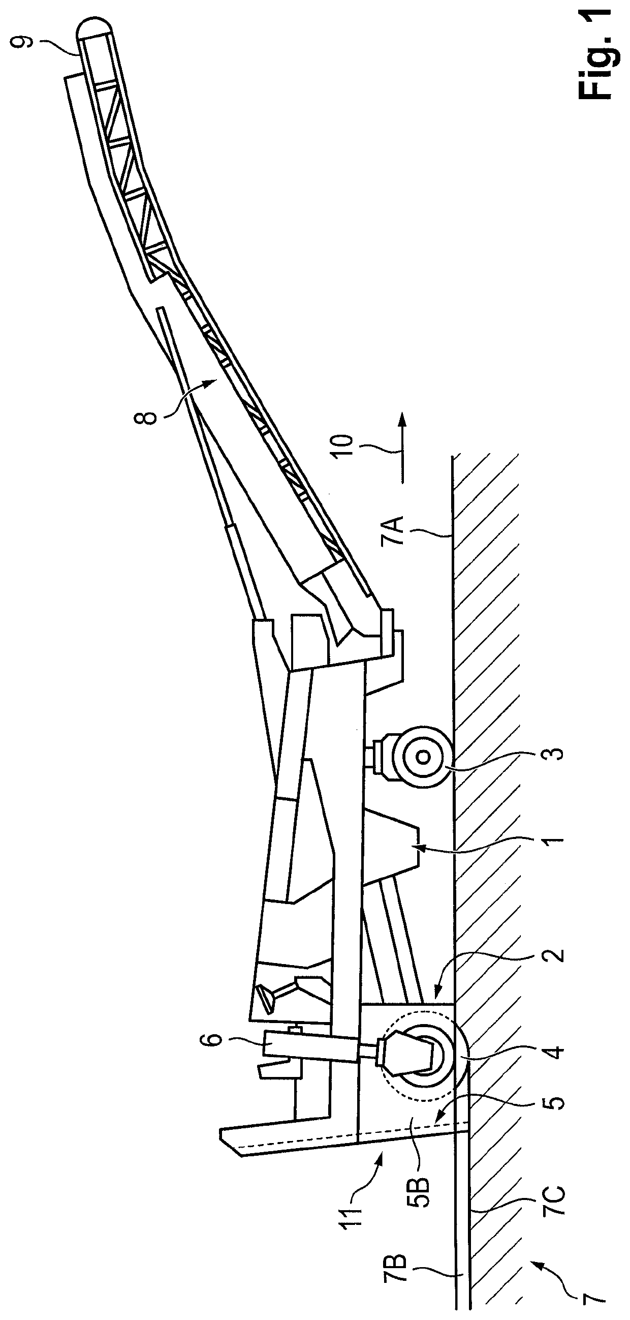
[0045]FIG. 1 shows the essential components of a road milling machine as an example of a self-propelled construction machine. The road milling machine has a machine frame 1 and a chassis 2 which can comprise front and rear wheels 3 or crawler drives. In the present embodiment, the road milling machine has a left and right rear wheel and only one front wheel 3. However, the road milling machine can also have a left and right front wheel.

[0046]In addition, the road milling machine has a milling drum 4 which is arranged in a milling drum housing 5 on the machine frame 1. In the present embodiment, the milling drum housing 5 is located at the rear of the machine.

[0047]In the present embodiment, the machine frame 1 can only be adjusted in height relative to the surface 7A of the ground 7 by means of rear piston / cylinder arrangements 6. The milling depth is adjusted by raising or lowering the machine frame 1 relative to the ground 7. However, the construction machine can also have a front...


PUM


Abstract

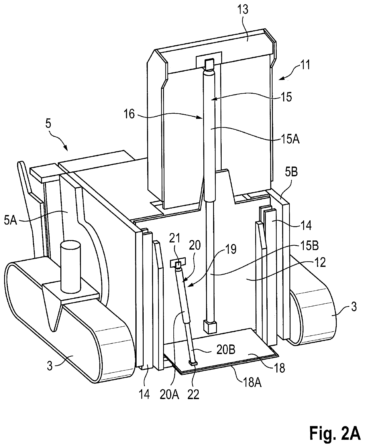
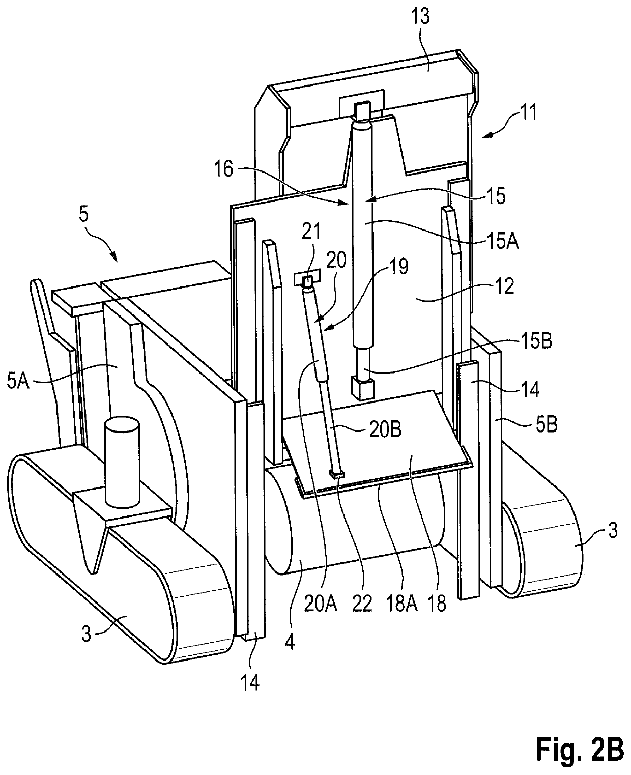
A self-propelled construction machine, in particular a road milling machine, recycler or stabiliser, having a machine frame and a milling drum which is arranged in a milling drum housing having a sealing device which has a sealing element arranged in the working direction of the construction machine behind the milling drum for closing the milling drum housing, an adjustment device for adjusting the height position of the sealing element in relation to the milling drum, and a controller for controlling the adjustment device of the sealing element. The sealing device has a scraper element, which is pivotably arranged on the sealing element such that the scraper element rests on the milled material, so that the scraper element is pulled over the milled material with the advancing construction machine and is pivoted in relation to the milling drum on the basis of the height of the milled material. The height position of the at least one sealing element is adjusted on the basis of the pivot position of the scraper element such that the pivot position of the scraper element is within a predetermined pivoting range when the construction machine advances.

Description

BACKGROUND OF THE INVENTIONField of the Invention[0001]The invention relates to a self-propelled construction machine, in particular a road milling machine, recycler or stabiliser, having a machine frame and a milling drum which is arranged in a milling drum housing having a sealing device which has at least one sealing element arranged in the working direction of the construction machine behind the milling drum for closing the milling drum housing, an adjustment device for adjusting the height position of the sealing element in relation to the milling drum, and a controller for controlling the adjustment device of the sealing element.Description of the Prior Art[0002]With the known road milling machines, the road surface can be milled off true to contour and evenly. A distinction must be made between road milling machines and so-called stabilisers or recyclers, which, by adding binding agents, produce a load-bearing substructure from a non-load-bearing substrate, for example, loose...

Claims


Application Information

Patent Timeline
IPC IPC(8): E01C23/088E01C23/12
CPCE01C23/088E01C23/127E01C21/00E01C23/065
Inventor BERNING, CHRISTIANSALZ, ANDREASQUADT, MARTIN
Owner WIRTGEN GMBH
Learn More