Eureka AIR delivers breakthrough ideas for toughest innovation challenges, trusted by R&D personnel around the world.

Device and method for measuring repeated positioning precision of robotic arm

a robotic arm and repeating positioning technology, applied in the field of repeating positioning precision measuring devices, can solve the problems of poor positioning precision of laser trackers, limited moving speed of robotic arms, slow tracking positioning speed of laser trackers, etc., and achieve cost-effective overall calibration modules, simple structure, and fast positioning speed

Active Publication Date: 2022-10-06
NAT CHUNG SHAN INST SCI & TECH
View PDF4 Cites 1 Cited by
  • Summary
  • Abstract
  • Description
  • Claims
  • Application Information

AI Technical Summary

Benefits of technology

The present invention provides a device and method for measuring the precision of a robotic arm's positioning. The device has a simple structure and can calibrate infinite numbers of positions and orientations with absolute precision of less than 0.1 μm. It has a fast positioning speed and is cost-effective. The device also uses three detection laser beams that have different operating wavelengths and a ±5 nm interferometric filter to filter out scattered light from the remaining two laser beams to ensure accurate measurements.

Problems solved by technology

First of all, a laser tracker has poor positioning precision, which aggravates as the tracking distance increases.
The positioning precision performance depends on the manufacturer brand, and is in general, approximately 25 μm at a distance of 5 m, and approximately 80 μm at a distance of 80 m. Secondly, the tracking positioning speed of a laser tracker is slow, and so the moving speed of a robotic arm is limited.
Thirdly, a corresponding measurement calibration system is more costly.
Moreover, measurement can be performed only within a predetermined range, and measurement devices perpendicular to one another have to be re-established for different positions, resulting in complications.

Method used


Image

  • Device and method for measuring repeated positioning precision of robotic arm
  • Device and method for measuring repeated positioning precision of robotic arm
  • Device and method for measuring repeated positioning precision of robotic arm

Examples


Embodiment Construction

[0025]To facilitate understanding of the object, characteristics and effects of this present disclosure, embodiments together with the attached drawings for the detailed description of the present disclosure are provided.

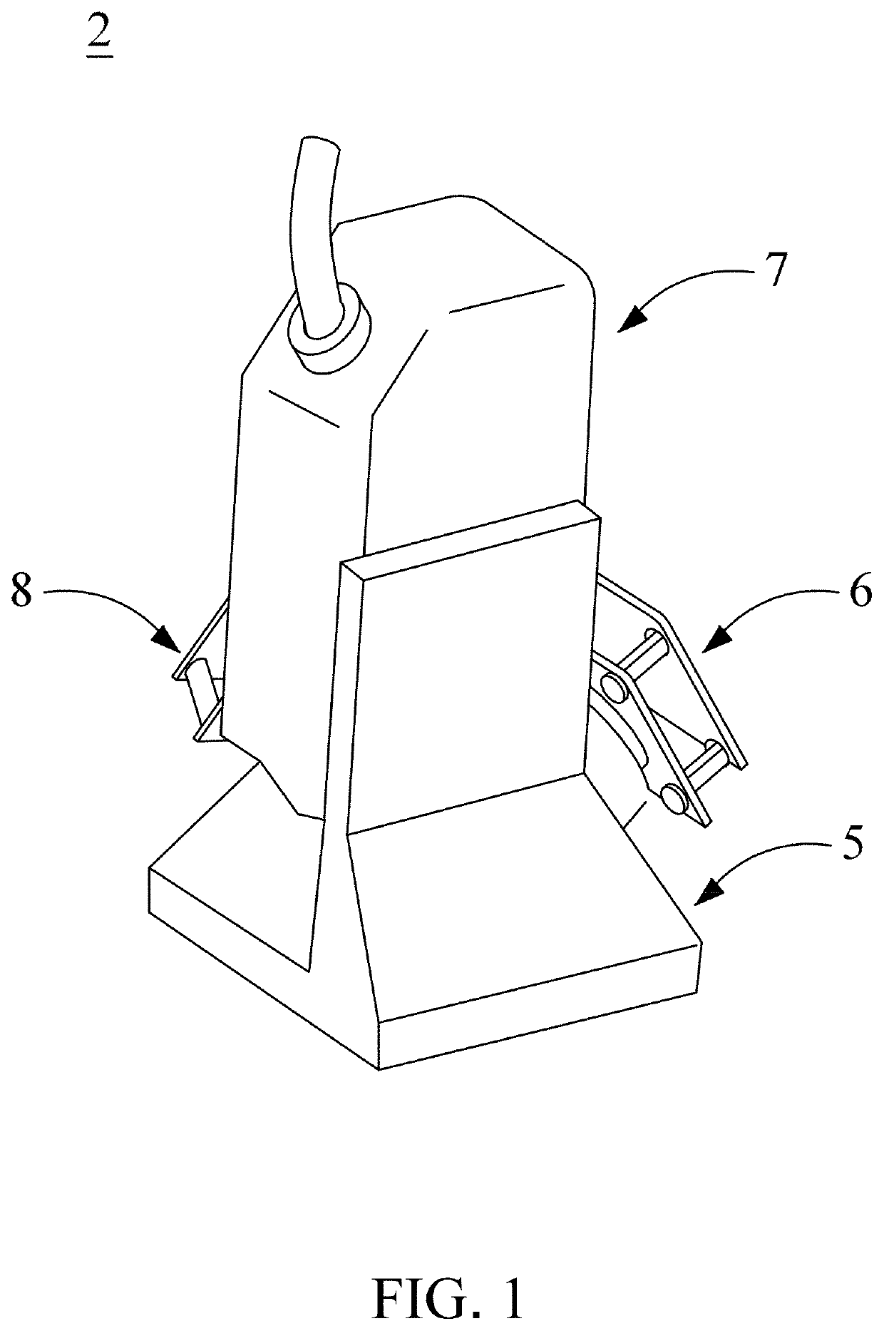
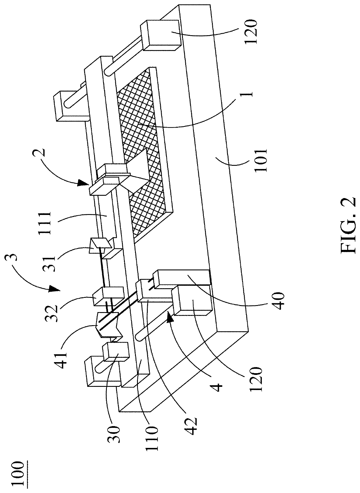
[0026]Refer to FIG. 1 to FIG. 9. The present invention provides a device for measuring repeated positioning precision of a robotic arm. Using an optical speckle three-dimensional displacement sensor 2 developed by the inventor and further in conjunction with an optical speckle image three-dimensional positioning base 1 having low thermal expansion and built with an optical speckle coordinate database, an optical speckle three-dimensional absolute positioning space is established. The optical speckle three-dimensional displacement sensor 2 is installed on a robotic arm end effector 21, a robotic arm 20 is moved to have the optical speckle three-dimensional displacement sensor 2 enter the optical speckle three-dimensional absolute positioning space of the optical spec...


PUM


Abstract

A device for measuring repeated positioning precision of a robotic arm is introduced. Using an optical speckle three-dimensional displacement sensor developed by the inventor, and with collaboration of an optical speckle image three-dimensional positioning base built with an optical speckle coordinate database and having low thermal expansion, an optical speckle three-dimensional absolute positioning space is established. The optical speckle three-dimensional displacement sensor is installed on an end effector of a robotic arm, the robotic arm is moved to have the optical speckle three-dimensional displacement sensor enter an optical speckle three-dimensional absolute positioning space, an optical speckle image of a positioning point is captured and compared with a coordinate optical speckle image in the optical speckle coordinate database, and current three-dimensional absolute positioning coordinates of the end effector of the robotic arm can be obtained.

Description

BACKGROUND OF THE INVENTION1. Field of the Invention[0001]The present disclosure relates to a device and a method for measuring repeated positioning precision of a robotic arm, and in particular to a device and a method capable of measuring precision of single-point repeated positioning of a robotic arm as well as precision of a motion track of repeated positioning of a robotic arm in an optical speckle three-dimensional absolute positioning space.2. Description of the Related Art[0002]Substituting robots for human labor has become a trend. Tractica has estimated that the market value of global robot revenue will go beyond USD 100 billion for the first time in the year 2020, and will even reach as high as USD 500 billion in the year 2025. That is, in the next six years, the revenue of the global robotic industry will grow for more than 500%, and the influence of robots on the human life is ever-increasing. Main technical parameters of robots generally include the seven parameters be...

Claims


Application Information

Patent Timeline
IPC IPC(8): B25J19/02B25J13/08B25J9/16
CPCB25J19/022B25J13/088B25J9/1692G05B2219/39024G05B2219/39033
Inventor HWANG, YI-YUHLIU, LI-CHUNG
Owner NAT CHUNG SHAN INST SCI & TECH
Why Eureka
Eureka Blog
Learn More