
Bicycle driving system and kit

a technology of auxiliary mid-drive system and bicycle frame, which is applied in the direction of cycle equipment, transportation and packaging, gearing, etc., can solve the problems of poor compatibility between the bicycle frame, insufficient ground clearance, and limited orientation of the auxiliary mid-drive system on the bottom bracket of the bicycle fram

Pending Publication Date: 2022-09-29
CYC MOTOR LTD
View PDF0 Cites 0 Cited by
  • Summary
  • Abstract
  • Description
  • Claims
  • Application Information

AI Technical Summary

Benefits of technology

This patent describes an auxiliary drive kit for bicycles that allows for easy customization and power adjustment. The kit includes a mounting unit for attaching a motor and deceleration unit to the bike, and a detachable second stage deceleration unit for connecting to the pedal assembly. The mounting unit can be adjusted for different bicycle structures, and includes support plates for secure mounting. The entire drive unit has a compact structure and is easy to mount, while the mounting unit allows for power adjustment in various models of bicycles on the market. The technical effects of this invention include increased safety, compact design, and flexibility for customization and power adjustment.

Problems solved by technology

This leads to a number of problems, including insufficient ground clearance after the mounting of the auxiliary mid-drive system to the bicycle bottom bracket and poor compatibility between different types and shapes of bicycle frame and the auxiliary mid-drive system.
The limited orientation of mounting the auxiliary mid-drive system on the bottom bracket of the bicycle frame is usually caused by the shape of the motor unit.
Another problem is that different bicycle frames of the prior art have different types of spindle (i.e. a turning part for connecting a left crank and a right crank in the bicycle frame, e.g. BSA 68-83, 100, 120, BB92 and BB107 on the market), and different standards of the spindle have different requirements for dimensions and securing methods of the spindle.
The lack of interchangeable parts on the existing auxiliary mid-drive system also causes problems of adaptability of the auxiliary mid-drive system for the spindle of different standards.
The prior art auxiliary mid-drive system used in bicycles cannot satisfy users' customization needs.

Method used


Image

  • Bicycle driving system and kit
  • Bicycle driving system and kit
  • Bicycle driving system and kit

Examples


Embodiment Construction

[0080]The invention will be further described below in conjunction with the specific embodiments and the drawings. More details are set forth in the following description for better understanding of the invention, although it is apparent that the invention may be embodied in various manners other than those described herein. Those skilled in the art may make extension and deduction depending on the practical application situations without departing from the spirit of the invention. Thus, the scope of the invention is not intended to be limited by the contents of the specific embodiments.

[0081]A common power component in a bicycle is a pedal assembly 80. The pedal assembly 80 usually comprises a pedal, crank 81, chainrings 82 and a spindle 83 (which is also called a BB spindle) mounted on a mounting part of a bottom bracket of the bicycle. The pedaling of a rider drives the crank 81 and the chainrings 82 to rotate. The rotation of the chainrings 82 is transferred through a chain to t...


PUM


Abstract

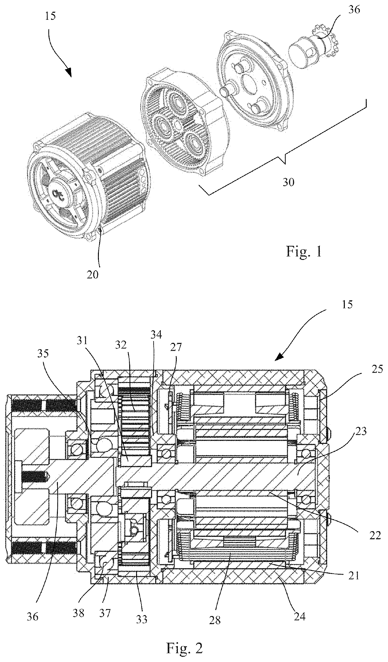
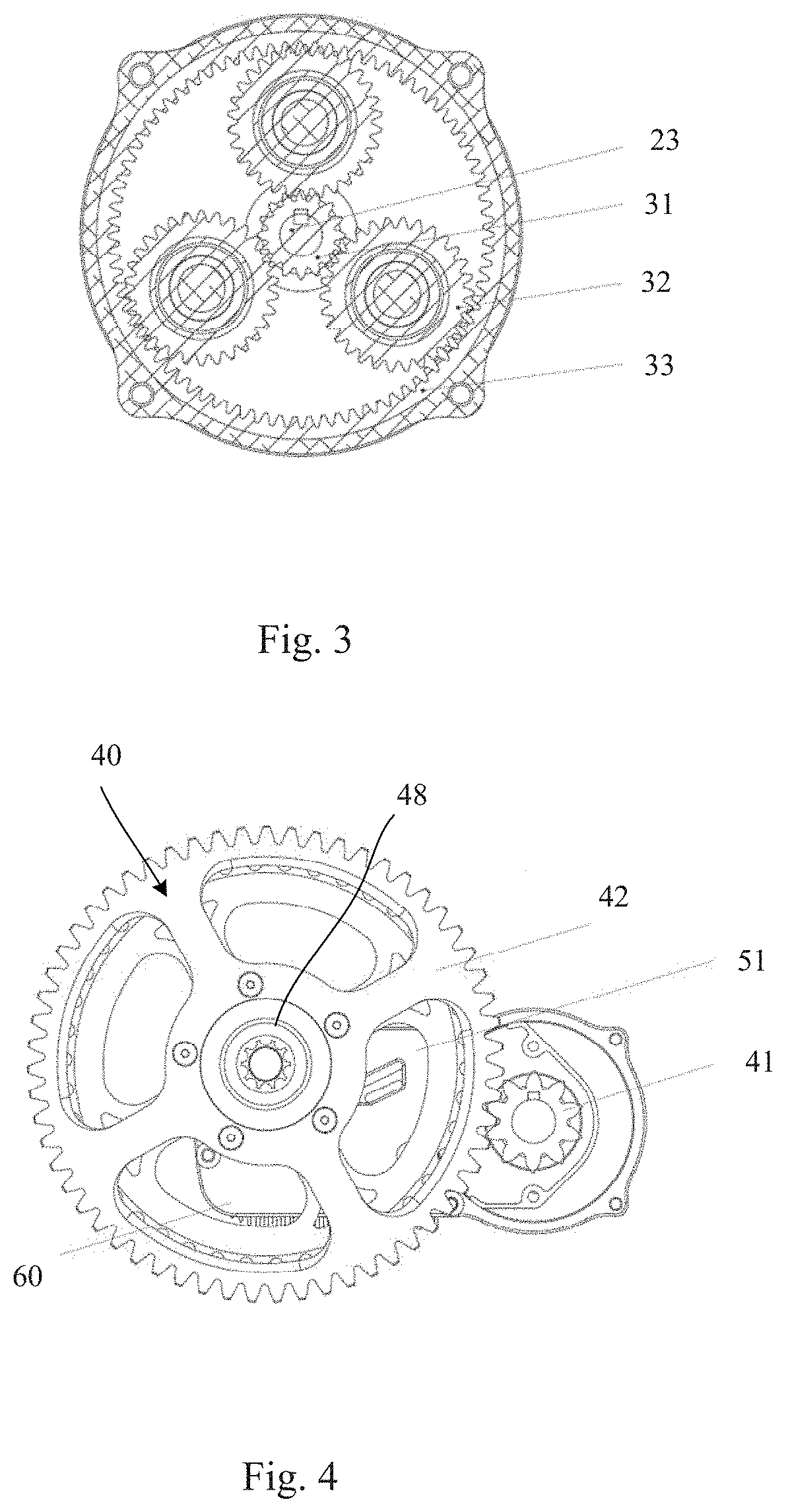
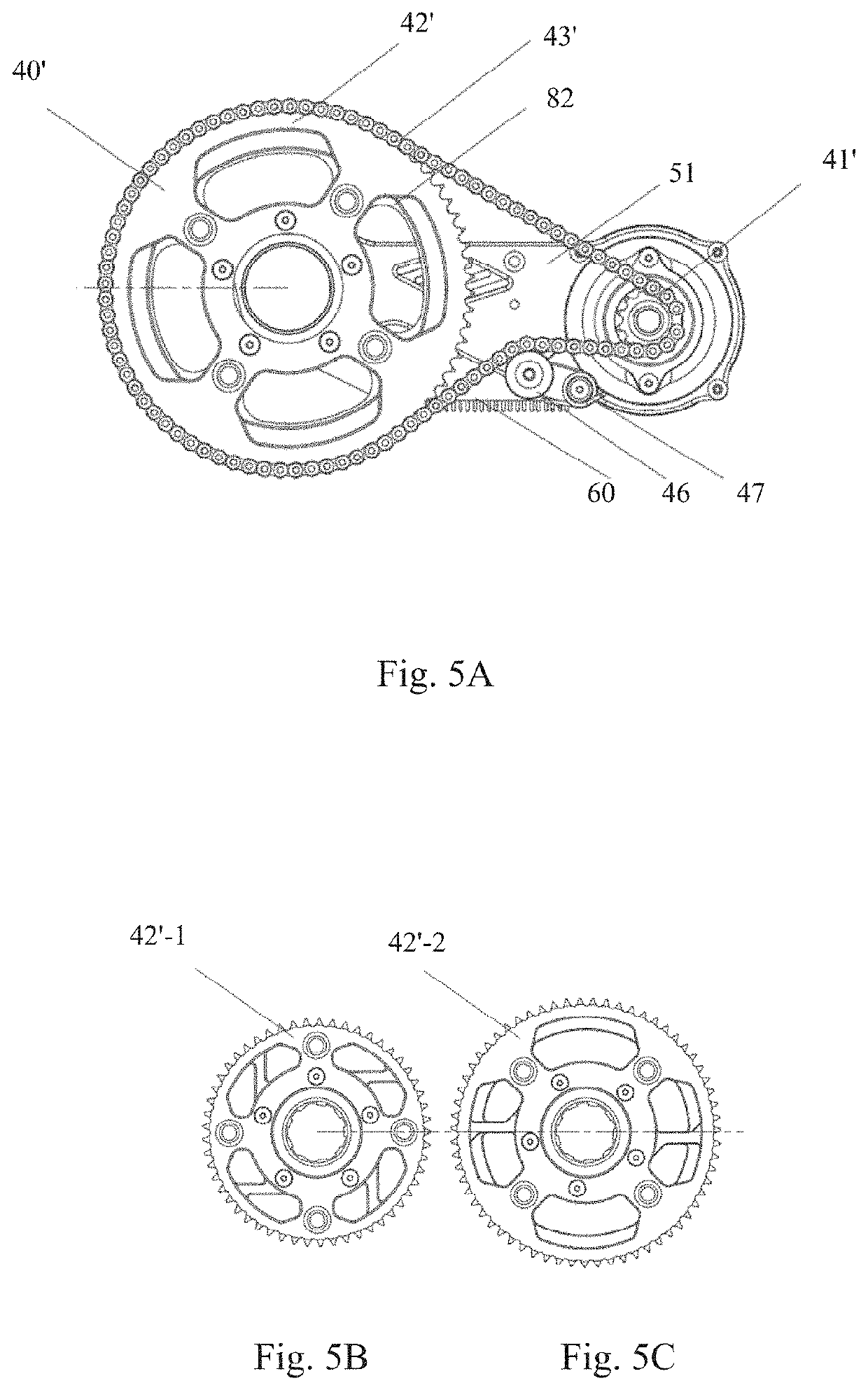
The invention discloses a bicycle drive system (10) and a kit. The drive system comprises a drive unit (15) comprising a housing, a motor unit (20) having a stator (21), a rotor (22) and an output shaft and accommodated in the housing, and a first stage deceleration unit (30) having an input part connected to the output shaft of the motor unit and an output part; a mounting unit (50) configured to secure and hold the drive unit on a bicycle body (70); and a second stage deceleration unit (40) arranged external to the drive unit and detachably mounted on the first stage deceleration unit for connection to a pedal assembly (80) to transfer a drive force from the output part of the first stage deceleration unit to chainrings (82) of the pedal assembly. The drive unit, the mounting unit and the second stage deceleration unit are each provided as a modular part for assembling to the bicycle. The invention provides a customizability of the drive system.

Description

FIELD OF THE INVENTION[0001]The invention relates to a bicycle drive system capable of providing power for a bicycle or providing for example a pedal assembly with power assist.BACKGROUND OF THE INVENTION[0002]In recent years, an auxiliary drive system to aid in providing an electric drive force for a bicycle has been developed to lessen physical exertion of a rider. The auxiliary drive system comprises an auxiliary mid-drive system configured to drive a pedal assembly of a bicycle, particularly to drive chainrings of the pedal assembly driven by a crank to transmit the drive force to bicycle wheels via a chain connected to the chainrings to provide the auxiliary drive, whereby to achieve the aim of saving stamina of the rider.[0003]A typical and common shortcoming of the existing auxiliary mid-drive system of the bicycle consists in that the dimensions of a motor are too large and the clearance between the motor and the bottom bracket shell of the bicycle is relatively small. This ...

Claims


Application Information

Patent Timeline
Patent Type & Authority Applications(United States)
IPC IPC(8): B62M6/55B62M6/50B62J45/412B62J45/421B62J45/411F16H37/02
CPCB62M6/55B62M6/50B62J45/412B62J45/421B62J45/411F16H37/02B62M11/145H02K7/116F16H37/041
Inventor CHAN, WAN HONG
Owner CYC MOTOR LTD
Learn More