Eureka AIR delivers breakthrough ideas for toughest innovation challenges, trusted by R&D personnel around the world.

Exhaust tool and exhaust system

a technology which is applied in the field of exhaust tool and exhaust system, can solve the problems of deteriorating sight, affecting the image of endoscope, and affecting the operation

Pending Publication Date: 2022-09-29
TRYTEC
View PDF0 Cites 0 Cited by
  • Summary
  • Abstract
  • Description
  • Claims
  • Application Information

AI Technical Summary

Benefits of technology

The present invention aims to provide an exhaust tool and system for use in surgery using endoscopes. The invention addresses the problem of mist generation during surgery and ensures easy attachment and discharge of the generated mist. The exhaust tool has holding portions that prevent movement of the exhaust tool position and may include frictional materials to achieve better holding of the tool.

Problems solved by technology

Such mist not only deteriorates the sight, but also adheres to the tip of the endoscope, thus causing stain on the lens thereof and deterioration of an endoscope image.
Therefore, the tip of an endoscope optical tube frequently needs to be cleaned and wiped, whereby the surgery is interrupted.
However, since the tip of the device at which mist is generated and the smoke discharging portion of the trocar sheath are distant from each other, there is a problem that it is difficult to efficiently discharge smoke.
More specifically, information needed for surgery using an endoscope is only image (visual) information obtained from the endoscope, and sight deterioration due to generation of mist such as water vapor or smoke in the abdominal cavity, and stain on an observation window portion of the endoscope, hamper safe surgery operation.
Therefore, during surgery, it takes time to wait until the mist is cleared or to extract the endoscope once to the outside of the body and clean the endoscope, so that the surgery time is prolonged, resulting in a great burden on a patient or a risk of causing an unexpected complication.
However, these are large-scale devices, require enormous cost, and require a wide installation space.
H8-196622 (JPH8-196622A) proposes an exhaust tube for surgery with an endoscope, but it is difficult to efficiently discharge mist in an abdominal cavity.

Method used


Image

  • Exhaust tool and exhaust system
  • Exhaust tool and exhaust system
  • Exhaust tool and exhaust system

Examples


Embodiment Construction

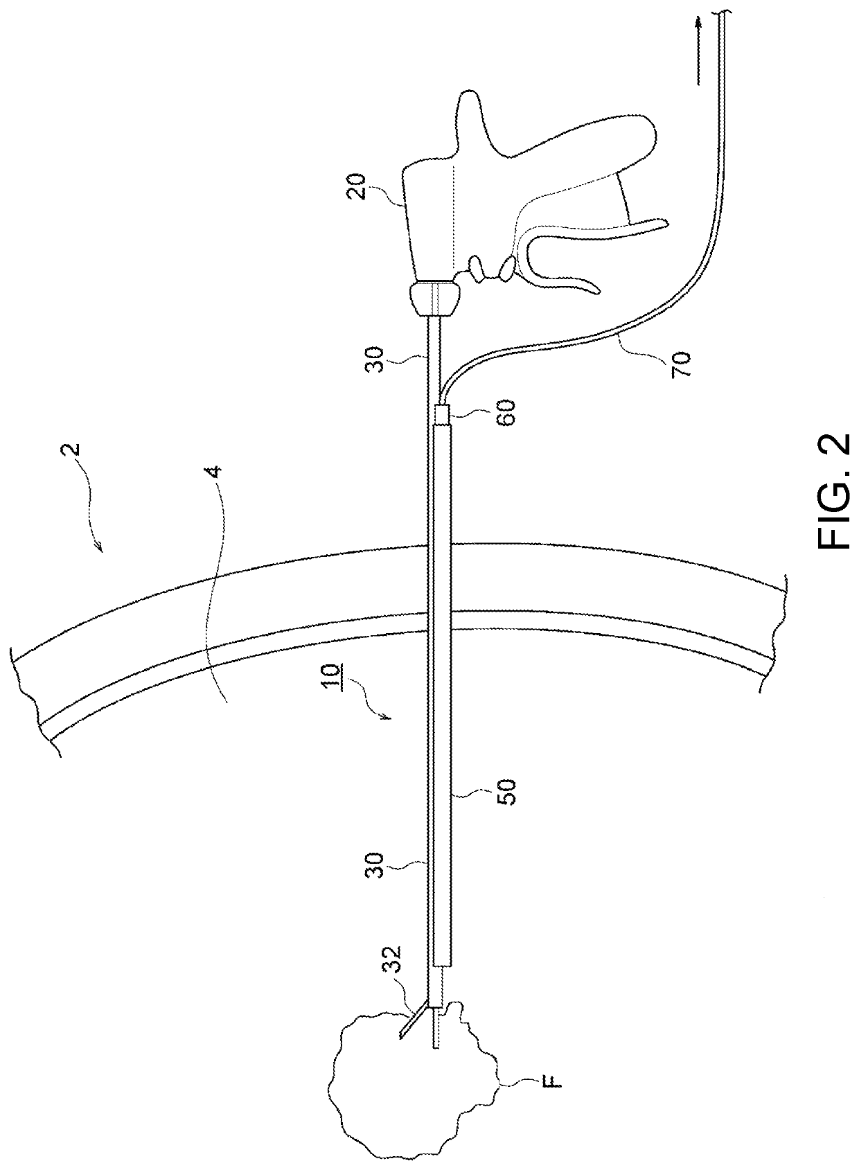
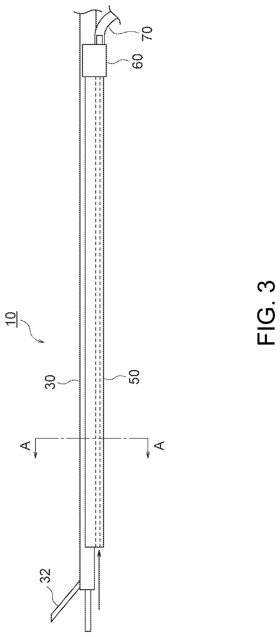
[0024]Hereinafter, an embodiment of the present invention will be described with reference to the drawings. FIG. 1 to FIG. 6 show an exhaust tool according to the present embodiment and an ultrasonic coagulation incision device to which the exhaust tool is attached. FIG. 7 is a side view of a conventional ultrasonic coagulation incision device.

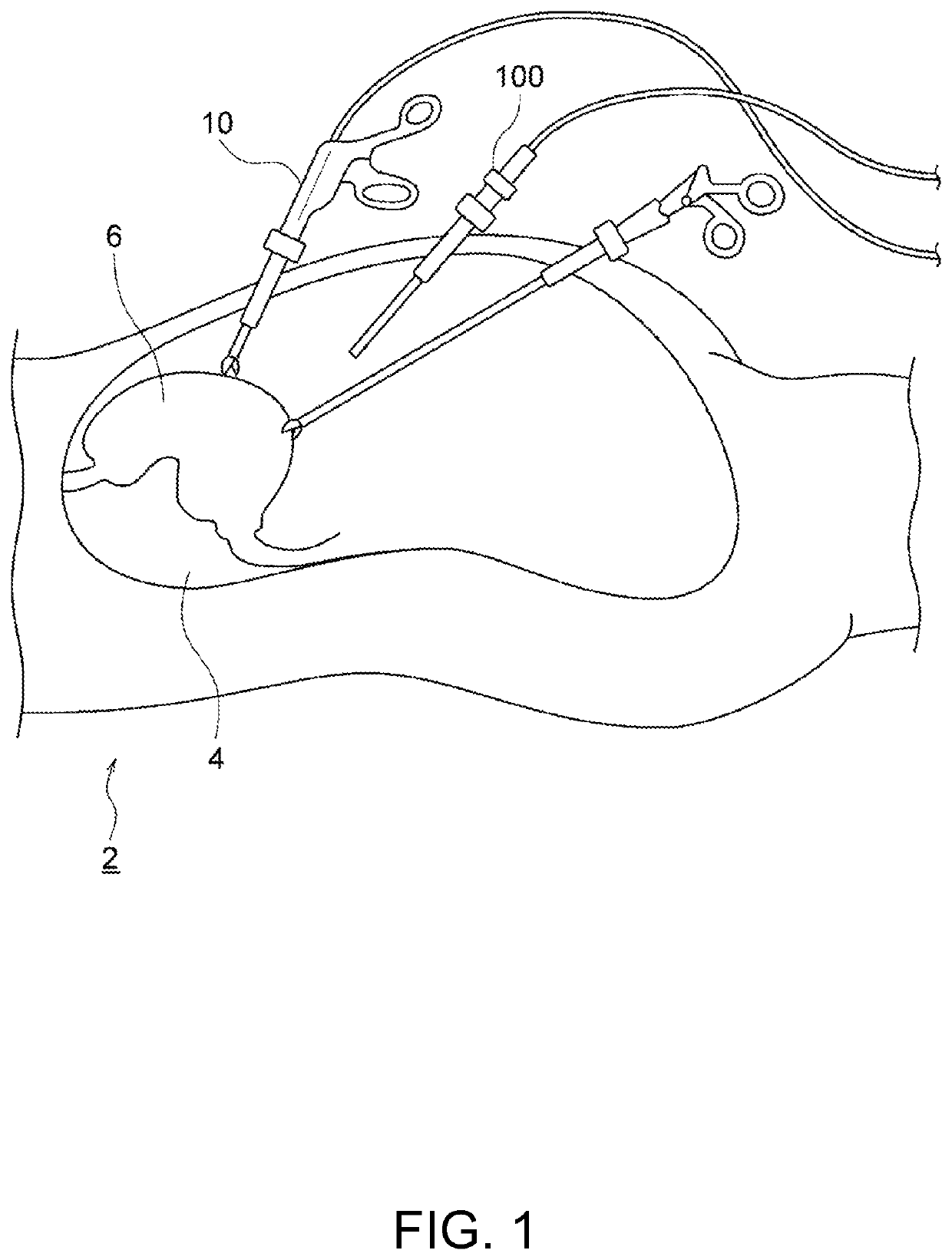
[0025]FIG. 1 schematically shows a case of performing surgery in an abdominal cavity 4 of a human body 2 by an ultrasonic coagulation incision device 10 to which an exhaust tool 50 according to the present embodiment is attached. As shown in FIG. 1, the ultrasonic coagulation incision device 10 and a laparoscope 100 are used in performing surgery on an organ 6 present in the abdominal cavity 4 of the human body 2, or the like. Specifically, carbon dioxide gas is injected into the abdominal cavity 4 of the human body 2 to inflate the abdominal cavity 4, and then coagulation and incision of organ tissue are performed by the ultrasonic coagulatio...


PUM


Abstract

An exhaust tool (50) includes: a flexible body portion (51) extending over substantially an entire length of a cylindrical shaft (30, 90) of an incision energy device (e.g., ultrasonic coagulation incision device 10 or electrocautery device 80) having an energy generation portion (32) for incision provided at a tip thereof; a pair of holding portions (52) provided to the body portion (51) and configured to hold the cylindrical shaft (30, 90); and a flow path formation portion (54) forming therein a flow path (56) for mist generated from the energy generation portion (32). The exhaust tool (50) is allowed to be attached / detached to / from the cylindrical shaft (30, 90) by the pair of holding portions (52) being opened through bending of the body portion (51).

Description

TECHNICAL FIELD[0001]The present invention relates to an exhaust tool and an exhaust system.BACKGROUND ART[0002]In recent years, in the medical field, surgical operations have been widely performed so as to perform incision or hemostasis operation on organ tissue using an energy device such as an electrocautery or an ultrasonic coagulation incision device, while observing the inside of a body cavity using an endoscope such as a laparoscope or a thoracoscope. The proportions of laparoscopic surgery and thoracoscopic surgery in surgical operations have been increasing year by year because of their low invasiveness, good aesthetic outcome, and the like.[0003]In performing surgery using an endoscope as described above, mist such as water vapor or smoke is generated due to heat at a part where a scalpel probe portion at the tip and organ tissue contact with each other. Such mist not only deteriorates the sight, but also adheres to the tip of the endoscope, thus causing stain on the lens ...

Claims


Application Information

Patent Timeline
Patent Type & Authority Applications(United States)
IPC IPC(8): A61B17/32A61B17/34
CPCA61B17/320092A61B17/3421A61B2017/3445A61B17/3417A61B2218/008A61B2217/005A61B18/085A61B2018/00589A61B18/1445A61B2017/0046
Inventor ETO, TADAAKITAKEZAKI, HIROSHI
Owner TRYTEC
Why Eureka
Eureka Blog
Learn More