
Transformer inductor combination device

a technology of transformers and inductances, applied in the direction of transformers/inductances magnetic cores, transformers/react mounting/support/suspension, cores/yokes, etc., can solve the problems of large footprint of combined devices, difficult to create combined transformers/inductor devices that retain suitable electrical properties and are easy to manufactur

Active Publication Date: 2022-09-15
VISHAY DALE ELECTRONICS INC
View PDF2 Cites 0 Cited by
  • Summary
  • Abstract
  • Description
  • Claims
  • Application Information

AI Technical Summary

Benefits of technology

The design achieves a reduced footprint and manufacturing cost while maintaining suitable electrical properties, providing a larger resonant inductance useful in resonant converter applications.

Problems solved by technology

However, the separate device result in a larger footprint than a combined device.
However, it is challenging to create a combined transformer / inductor device that retains suitable electrical properties and is easy to manufacture.

Method used


Image

  • Transformer inductor combination device
  • Transformer inductor combination device
  • Transformer inductor combination device

Examples


Embodiment Construction

[0035]Directional phrases used herein, such as, for example, left, right, front, back, top, bottom and derivatives thereof, relate to the orientation of the elements shown in the drawings and are not limiting upon the claims unless expressly recited therein.

[0036]As employed herein, the term “number” shall mean one or an integer greater than one (i.e., a plurality).

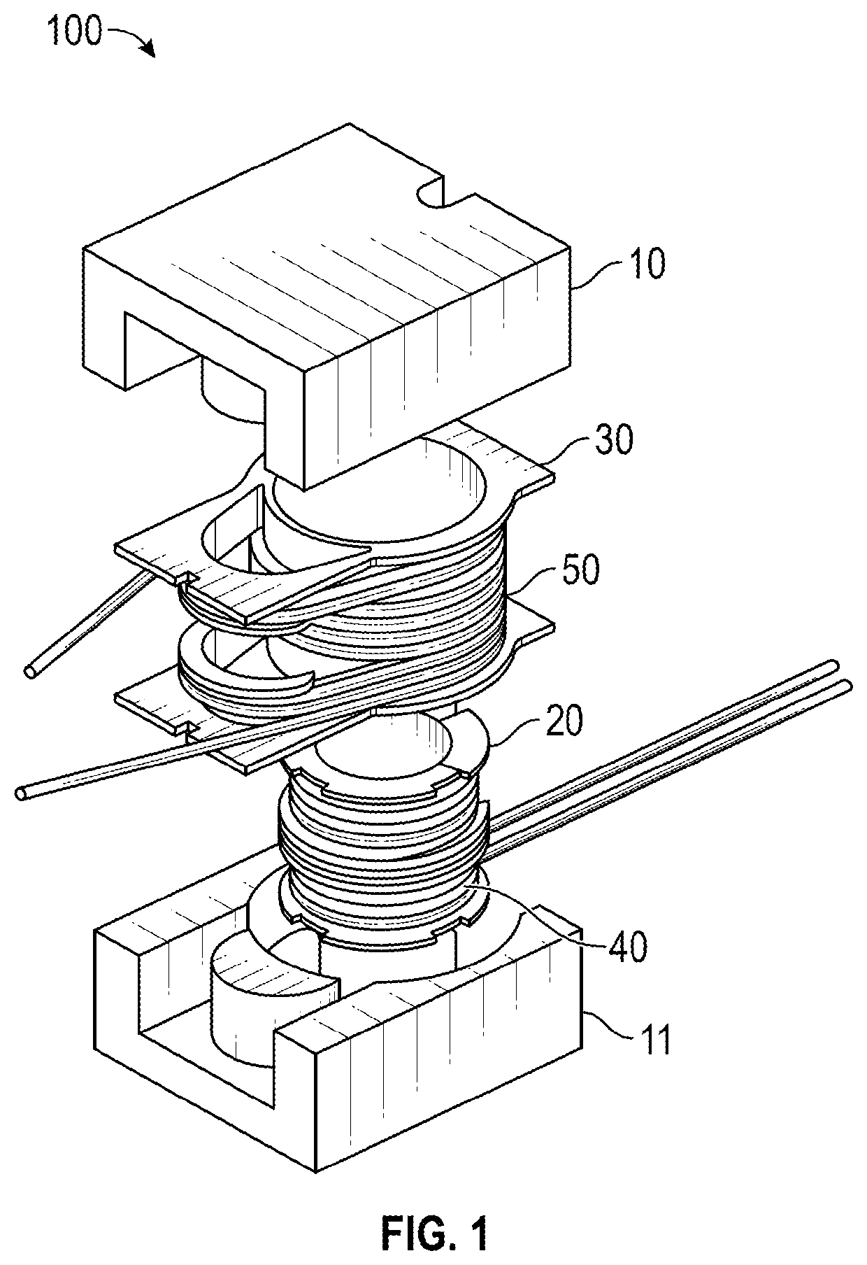
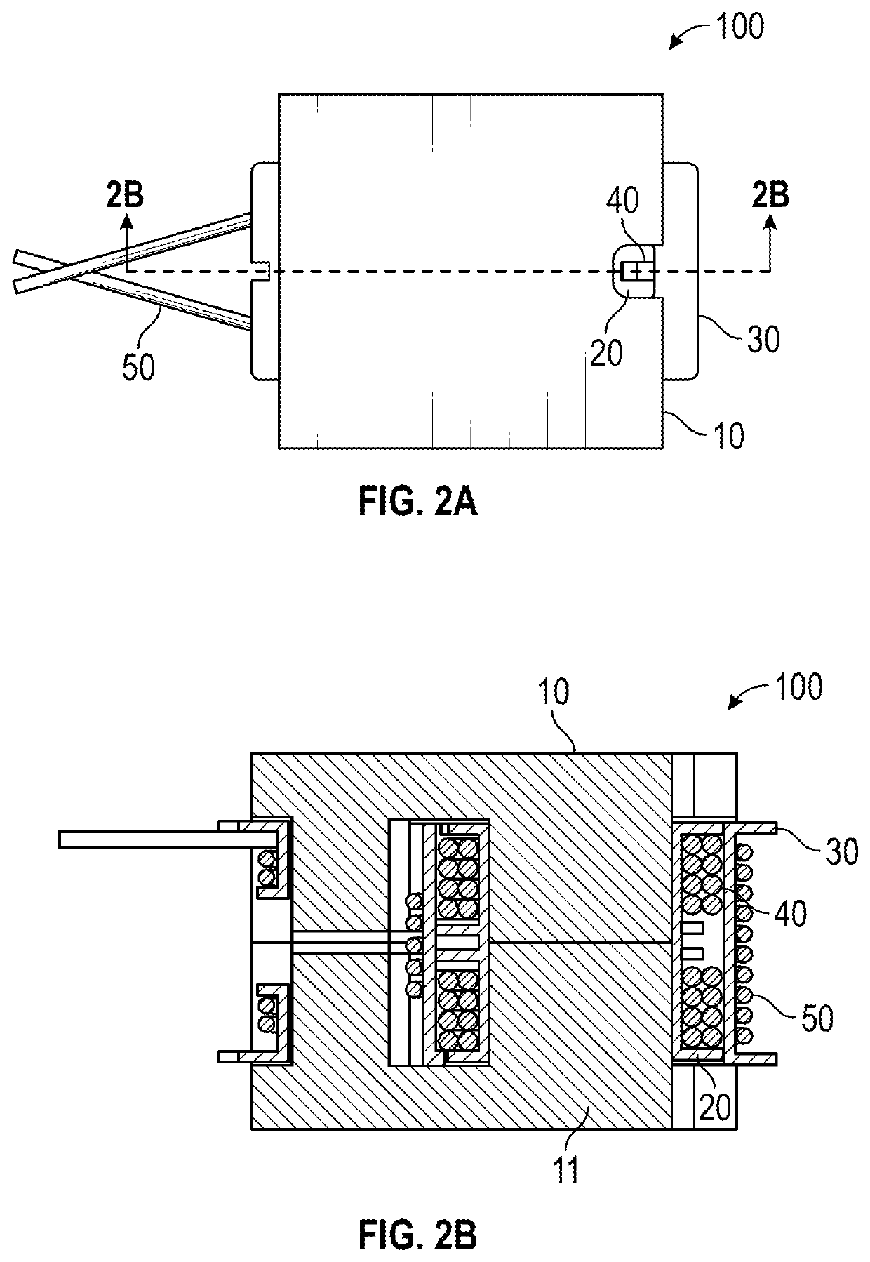
[0037]FIG. 1 is an exploded assembly view of a combined transformer / inductor device 100 in accordance with an exemplary embodiment of the disclosed concept. FIG. 2A is a top view of the assembled combined transformer / inductor device 100 and FIG. 2B is a section view of the assembled combined transformer / inductor device 100.

[0038]The combined transformer / inductor device 100 includes a core 10,11, an inner bobbin 20, and an outer bobbin 30. The inner bobbin 20 is wound with a first winding 40 and the outer bobbin 30 is wound with a second winding 50. The first winding 40 forms one winding of a transformer and the second win...


PUM

PropertyMeasurementUnit
resonant inductanceaaaaaaaaaa
heightaaaaaaaaaa
air gapaaaaaaaaaa

Abstract

A combined transformer / inductor device includes a core having a central core leg and an outer core leg spaced apart from the central core leg, an inner bobbin disposed around the central core leg, an outer bobbin disposed around the inner bobbin and the central core leg and having an upper portion having a first oblong portion disposed around the outer core leg, a lower portion having a second oblong portion disposed around the outer core leg, and a central portion disposed around the inner bobbin and the central core leg, a first winding wound around the inner bobbin, and a second winding wound around the outer bobbin, the second winding having a first portion wound around the first oblong portion, a second portion wound around the central portion, and a third portion wound around the second oblong portion.

Description

CROSS-REFERENCE TO RELATED APPLICATIONS[0001]This application is a divisional application of and claims priority to U.S. patent application Ser. No. 16 / 661,408, filed Oct. 23, 2019, entitled TRANSFORMER INDUCTOR COMBINATION DEVICE, which claims priority from U.S. Provisional Patent Application Ser. No. 62 / 873,468, filed Jul. 12, 2019, entitled “TRANSFORMER INDUCTOR COMBINATION DEVICE”, the contents of each of which are incorporated herein by reference.BACKGROUNDField[0002]The disclosed concept relates generally to electrical components, and more particularly, to magnetic devices such as inductors and transformers.Background Information[0003]Resonant converters are used in a variety of applications such as power conversion. For example, resonant converters are commonly used in automotive charging applications. Resonant converters are also employed in a variety of other industries such as alternate energy, military, and industrial applications.[0004]Resonant converters typically inclu...

Claims


Application Information

Patent Timeline
Patent Type & Authority Applications(United States)
IPC IPC(8): H01F27/26H01F17/04H01F27/02H01F3/08H01F27/29H01F27/28H01F27/06H01F5/02H01F27/24
CPCH01F27/26H01F17/043H01F27/027H01F3/08H01F27/29H01F27/2823H01F27/06H01F5/02H01F27/24H01F2005/022H01F27/325H01F27/40H01F27/38H01F27/306H01F27/303
Inventor EBNER, JASONFOLEY, MATTHEW
Owner VISHAY DALE ELECTRONICS INC
Learn More