KPI-Based Tilt Range Selection

Pending Publication Date: 2022-08-11
TELEFON AB LM ERICSSON (PUBL)
View PDF0 Cites 1 Cited by
  • Summary
  • Abstract
  • Description
  • Claims
  • Application Information

AI Technical Summary

Benefits of technology

The patent describes a method for optimizing the performance of mobile networks using a system called the Ericsson Cell Optimizer. This method involves a step-by-step process where the system selects the best solution based on technical considerations and restrictions. The process can be time-consuming and requires a lot of expert knowledge. The patent proposes a solution to reduce the amount of human input required, making the optimization process faster and more automated.

Problems solved by technology

Generating an optimal RF design involves a complex trade-off between capacity, coverage and quality.
The improvement of one of these metrics may, however, imply degradation in the other two.
In this sense, higher signal level provokes higher interference in the adjacent cells.
Such a process is both time and labour intensive.
Another source of cost is the need for a drive tests measurement campaign, which provides engineers with the necessary inputs to take their adjustment decisions.
As such, manual RF tuning may result in significant variability and a lack of consistency in the adjustment recommendations.
Furthermore, antenna configuration adjustments are typically determined on a cell-by-cell basis, and it is complicated to come up with final solutions that imply coordinated adjustment of multiple cells at the same time to maximize the QoS in a whole network area.
Furthermore, where different engineers are responsible for the RF tuning of different cells, any variability or lack of coordination in their approach may further reduce the extent to which the RF design is optimized.
Moreover, automatic approaches reduce the risk of implementing a poor plan that would happen when relying on making changes based on poor “expert intuition”.
These parameters that require a manual adjustment are sensitive to errors in database storage.

Method used


Image

  • KPI-Based Tilt Range Selection
  • KPI-Based Tilt Range Selection
  • KPI-Based Tilt Range Selection

Examples


Embodiment Construction

[0046]Example embodiments of the present invention will now be described in detail with reference to the accompanying drawings.

[0047]Where technical features in the drawings, detailed description or any claim are followed by reference signs, the reference signs have been included for the sole purpose of increasing the intelligibility of the drawings, detailed description, and claims. Accordingly, neither the reference signs nor their absence have any limiting effect on the scope of any claim elements.

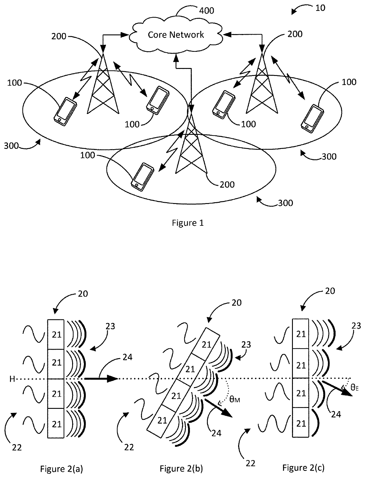
[0048]FIG. 1 is a schematic illustration showing a radio communication system 10, according to an example aspect herein. The radio communications system 10, and exemplary wireless telecommunication network, comprises a plurality of user equipments (UE) 100 and a plurality of radio base stations 200. Each radio base station 200 may, as in the present embodiment, be a LTE-A eNodeB. Alternatively, the radio base station may be, for example, a 5G gNB (next generation NodeB), LTE eNodeB, a 3...


PUM


Abstract

A computer-implemented method for determining a tilt range for each cell (300) of a plurality of cells of a wireless cellular telecommunications network, each cell (300) having at least one antenna (20). The method comprises the steps of: for each cell (300) of the plurality of cells, determining a value for each of a plurality of metrics, the plurality of metrics comprising: a metric indicative of retainability, a metric indicative of capacity, a metric indicative of uplink, UL, quality, a metric indicative of downlink, DL, quality, and a cell parameter; determining respective thresholds for each metric; for each cell (300) of the plurality of cells, classifying the cell (300) into one of a plurality of categories based on a comparison of the determined values of the plurality of metrics of the cell (300) to the corresponding thresholds, wherein each category of the plurality of categories has an associated range of tilt values; and determining, for each cell (300) of the plurality of cells, the tilt range for that cell (300) as the range of tilt values associated with the category into which the cell (300) is classified.

Description

TECHNICAL FIELD[0001]The present invention generally relates to the field of radiofrequency design and optimization. In particular, the present invention is directed to apparatuses and methods for determining a suitable tilt range for a plurality of antennae in a plurality of cells in a wireless cellular telecommunications network.BACKGROUND[0002]Radiofrequency (RF) design in a wireless cellular telecommunication network fully conditions the overall Quality of Service (QoS) perceived by subscribers. Generating an optimal RF design involves a complex trade-off between capacity, coverage and quality. This is extremely important for LTE, specifically for interference control, since either frequency planning (GSM) or soft-handover (UMTS) is not available, and one-to-one reuse is the most common frequency deployment to maximize spectrum efficiency.[0003]QoS can be considered as a combination of coverage, quality and capacity. While coverage may be defined as the area in which the receive...

Claims


Application Information

Patent Timeline
IPC IPC(8): H04W16/28H04W24/02H04W24/08
CPCH04W16/28H04W24/08H04W24/02
Inventor TOSYALI, ORKUNNEOPHYTOU, CHRISTOSOUTES CARNERO, JOSE
Owner TELEFON AB LM ERICSSON (PUBL)
Why Eureka
Try Eureka