
Rotating detonation engine

Pending Publication Date: 2022-07-28
PHYSICAL SCI
View PDF7 Cites 0 Cited by
  • Summary
  • Abstract
  • Description
  • Claims
  • Application Information

AI Technical Summary

Benefits of technology

This patent describes a new design for a rotating detonation engine that solves the problem of inefficient thrust production. The engine uses a cone-shaped detonation channel, eliminating the need for an abrupt constriction and reducing heat loss. The detonation channel has a smooth transition from inward to outward, and the engine includes an injection region that directs reactants inward with an angle matching the angle of the detonation channel. This design improves detonation stability, thrust efficiency, combustion efficiency, and ease of implementation.

Problems solved by technology

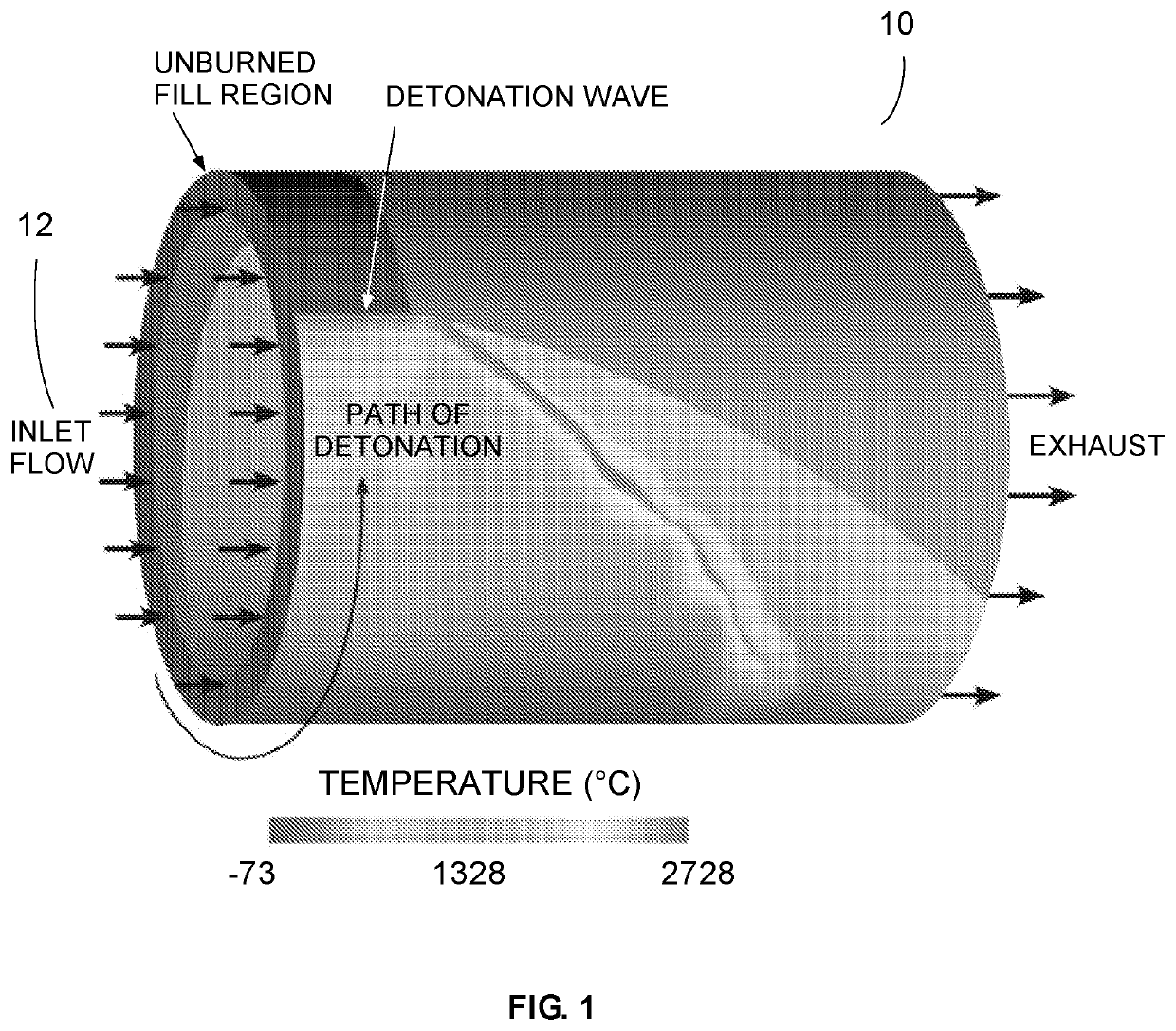
The problem of operating a rotating detonation engine where continuously rotating detonations traveling around a straight cylindrical detonation channel produce thrust inefficiently is solved, in one example, by using a cone-shaped detonation channel rather than a cylindrical detonation channel, eliminating the cylindrical section of the channel and drawing the walls towards the axial centerline of the engine.

Method used


Image

  • Rotating detonation engine
  • Rotating detonation engine
  • Rotating detonation engine

Examples


Embodiment Construction

[0041]Aside from the preferred embodiment or embodiments disclosed below, this invention is capable of other embodiments and of being practiced or being carried out in various ways. Thus, it is to be understood that the invention is not limited in its application to the details of construction and the arrangements of components set forth in the following description or illustrated in the drawings, if only one embodiment is described herein, the claims hereof are not to be limited to that embodiment. Moreover, the claims hereof are not to be read restrictively unless there is clear and convincing evidence manifesting a certain exclusion, restriction, or disclaimer.

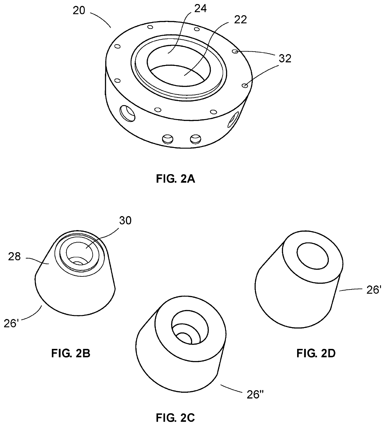
[0042]In some embodiments, a detonation channel is formed that is not parallel with the axial centerline of the engine, creating a cone-shaped annulus rather than a cylinder-shaped annulus. The engine may employ fuel and oxidizer injector(s) at an angle corresponding to the angle of the cone-shaped annulus, such that reacta...


PUM


Abstract

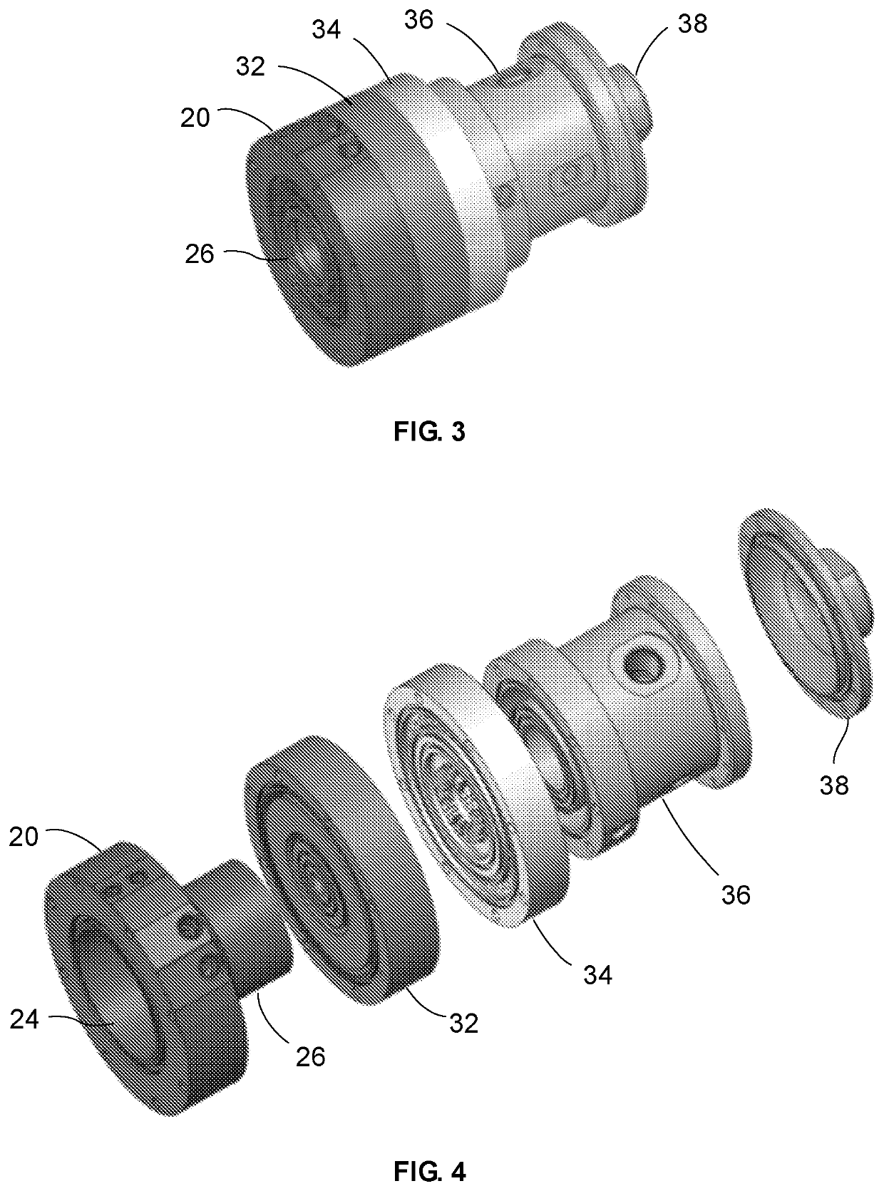
A rotating detonation engine includes an outer body with an opening therethrough having an interior wall and an inner body received in the outer body opening and with an outer wall tapering in the flow direction of the engine and spaced from the outer body opening interior wall defining a non-cylindrical improved efficiency detonation channel between the inner body outer wall and outer body opening interior wall.

Description

RELATED APPLICATIONS[0001]This application claims benefit of and priority to U.S. Provisional Application Ser. No. 63 / 141,542 filed Jan. 26, 2021, under 35 U.S.C. §§ 119, 120, 363, 365, and 37 C.F.R. § 1.55 and § 1.78, which is incorporated herein by this reference.GOVERNMENT RIGHTS[0002]This invention was made with U.S. Government support under Contract No. FA9300-19-P-1010 awarded by the U.S. Air Force. The Government may have certain rights in the subject invention.FIELD OF THE INVENTION[0003]This invention relates to the field of combustion and propulsion whereby rotating detonation engines are used to produce energy or thrust.BACKGROUND OF THE INVENTION[0004]Rotating detonation engines burn reactants using detonation combustion rather than deflagration combustion. Detonation processes represent a more efficient thermodynamic cycle than deflagration processes, giving rotating detonation engines the potential to exceed the efficiencies of conventional combustion devices in rocket...

Claims


Application Information

Patent Timeline
IPC IPC(8): F02K9/66
CPCF02K9/66F02K9/62F02C5/02F23R7/00F02K7/02
Inventor WEGENER, JEFFREY L.FARRELL, CHRISTOPHER T.
Owner PHYSICAL SCI
Learn More