
Angle adjustment stage device for dental technique

a technology of adjustment stage and dental technique, which is applied in the field of angle adjustment stage device for dental technique, can solve the problems of difficult maintenance, high cost of angle adjustment stage device, and long time to get familiar with the operation of the device, and achieve the effects of reducing device manufacturing cost, miniaturizing the device, and convenient device configuration

Pending Publication Date: 2022-07-14
IBA NOBUYUKI
View PDF0 Cites 1 Cited by
  • Summary
  • Abstract
  • Description
  • Claims
  • Application Information

AI Technical Summary

Benefits of technology

The present invention reduces the number of parts in an angle adjustment stage device, making it easier to manufacture, maintain, and operate. This also makes it easier for users to adjust the angle of the stage, as they only need to operate a few parts. Even beginners can quickly master the operation of the device.

Problems solved by technology

However, this angle adjustment stage device is still expensive and is not easy to maintain.
In addition, it takes a long time to get familiar with the operation of the device.

Method used


Image

  • Angle adjustment stage device for dental technique
  • Angle adjustment stage device for dental technique
  • Angle adjustment stage device for dental technique

Examples


Embodiment Construction

[0035]A preferred embodiment of the present invention will be explained below with reference to accompanying drawings.

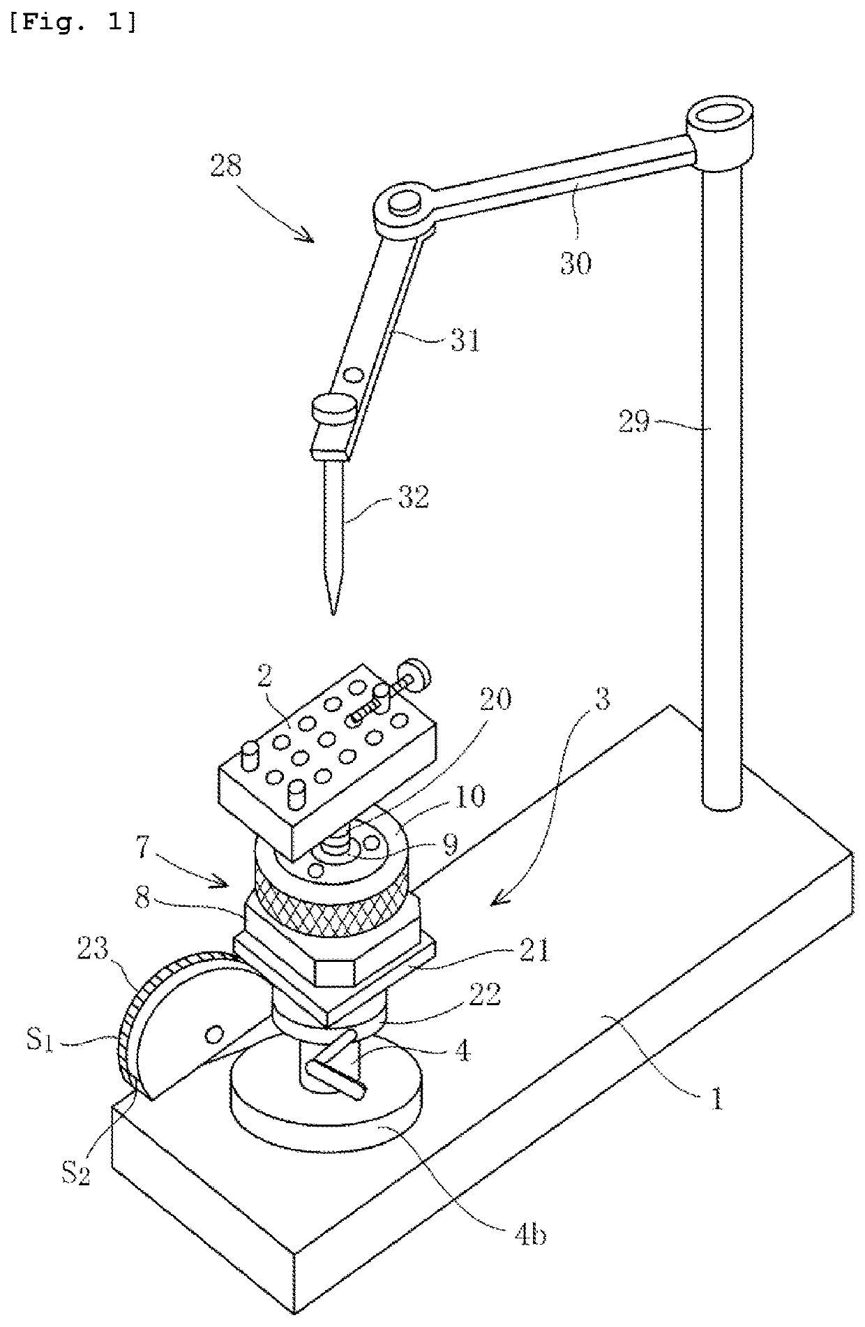
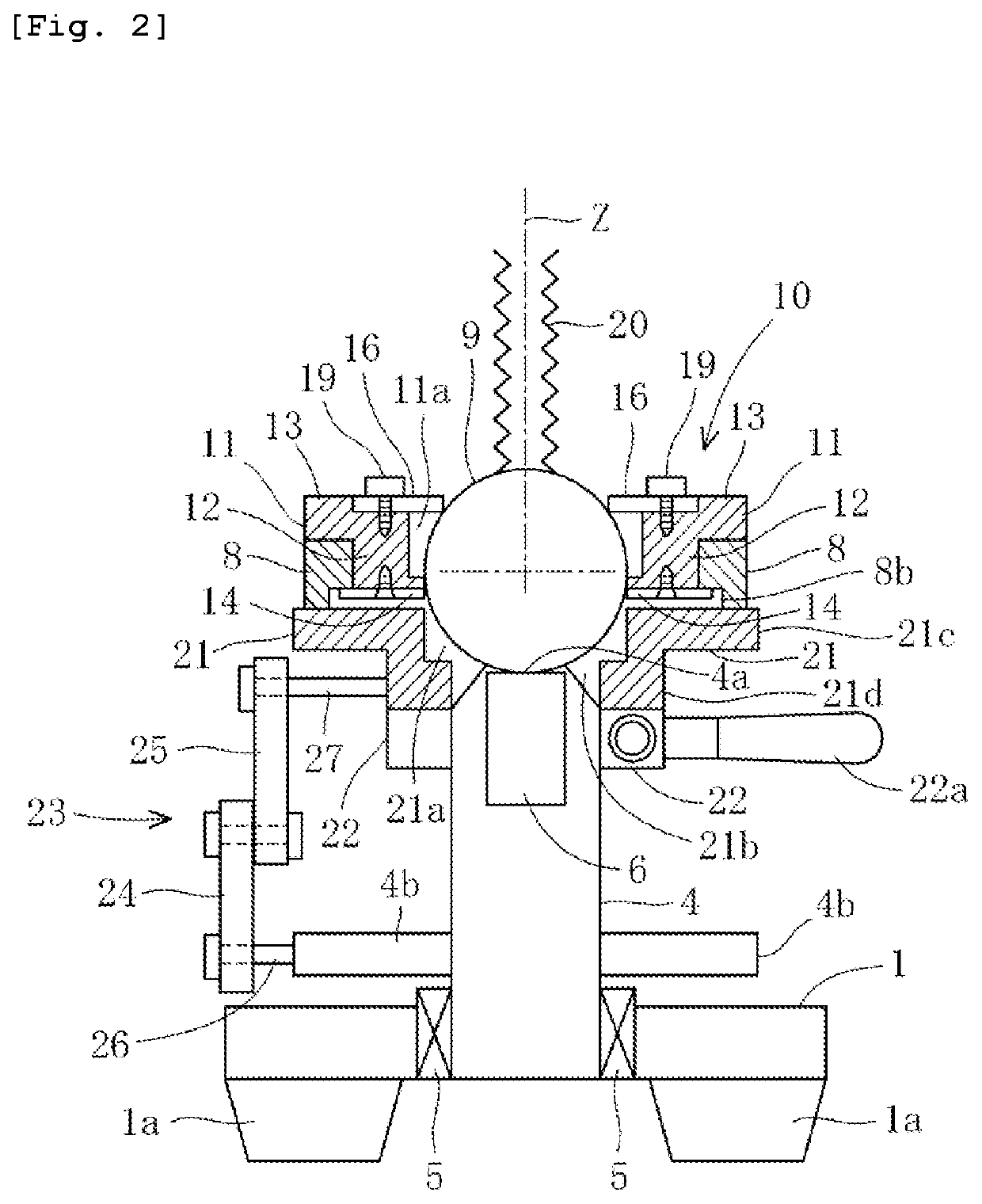
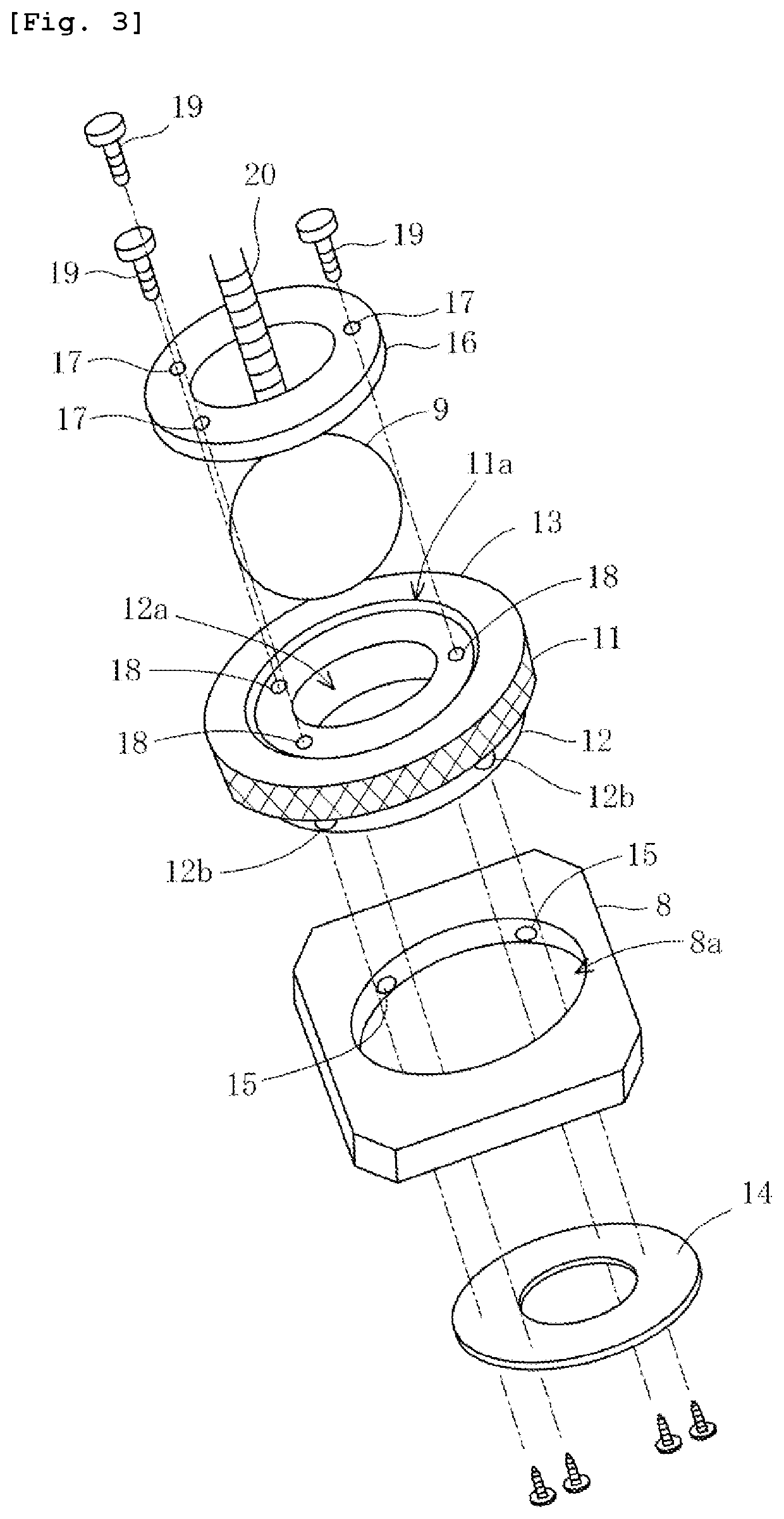
[0036]FIG. 1 is a perspective view of an angle adjustment stage device for dental technique according to an embodiment of the present invention, and FIG. 2 is a longitudinal section a stage support mechanism of the angle adjustment stage device for dental technique shown in FIG. 1. FIG. 3 is a disassembled perspective view of a rocking body of the angle adjustment stage device for dental technique shown in FIG. 1, and FIG. 4 is a side view of the angle adjustment stage device for dental technique shown in FIG. 1.

[0037]Referring to FIG. 1, an angle adjustment stage device of the present invention comprises a base 1, a stage 2 arranged above the base 1, a workpiece W for dental technique being fixed on the stage 2, and a stage support mechanism 3 provided on the base 1 to support the stage 2 in a manner such that a tilt angle of the stage 2 is adjustable,

[0038]In this ...


PUM


Abstract

A base shaft 4 with a built-in magnet is rotatably projected on a base 1. A rocking body 7 has a square substrate 8, a sphere 9, a sphere holder 10 rotatable around an axis which extends through the center of the substrate and perpendicular to the substrate, and a stopper for fixing the sphere holder at a desired rotational position. The sphere holder holds the sphere in such a way that the sphere is fixed at a desired rotational position. A stage is attached to the sphere through a support rod 20. A lower portion of the sphere protrudes downward from the sphere holder and substrate. The rocking body is magnetically coupled to the base shaft at a lower end of the sphere. An elevating body 21 is fitted on the base shaft and fixed by a set collar 22 at a desired height. The elevating body has a recess for receiving the lower portion of the sphere. The rocking body takes a horizontal position when the elevating body is brought into contact with the substrate of the rocking body, but takes a tilt position when a side of the substrate is brought into contact with an upper surface of the elevating body after the elevating body is lowered. An angle display mechanism 23 displays a tilt angle at the tilt position of the rocking body depending on the height of the elevating body.

Description

TECHNICAL FIELD[0001]The present invention relates to an angle adjustment stage device for dental technique, particular to, an angle adjustment stage device used in design of a hook and a base of a removable partial denture for replacement of missing teeth.BACKGROUND ART[0002]FIG. 8 is a perspective view of an example of a removable partial denture mounted on a plaster model.[0003]As shown in FIGS. 8(A) and 8(B), the removable partial dentures 33 comprise artificial teeth 34 and clasps 36 engaged with clasped teeth 35 adjacent to the removable partial dentures 33.[0004]In manufacturing process of the removable partial denture 33, firstly, a plaster model 37 is made by modeling target teeth and mucous membranes from a patient's mouth cavity, and the clasped teeth 35 for the removable partial dentures 33 are chosen from residual teeth of the plaster model 37, and then the clasps 36 are designed and produced in such a way that they fit the curved surfaces of the clasped teeth 35.[0005]...

Claims


Application Information

Patent Timeline
IPC IPC(8): A61C13/36A61C13/01
CPCA61C13/1016A61C13/01A61C13/12A61C19/04A61C19/055
Inventor IBA, NOBUYUKI
Owner IBA NOBUYUKI
Learn More