
Outboard motor engine cover and outboard motor

a technology for outboard motors and engine covers, applied in the direction of propulsive elements, marine propulsion, vessel construction, etc., can solve the problems of inability to lighten the restrictions imposed on the shape or the like, and inability to effectively reduce the total number of parts obtained by dividing the top cowl

Pending Publication Date: 2022-06-30
YAMAHA MOTOR CO LTD
View PDF4 Cites 0 Cited by
  • Summary
  • Abstract
  • Description
  • Claims
  • Application Information

AI Technical Summary

Benefits of technology

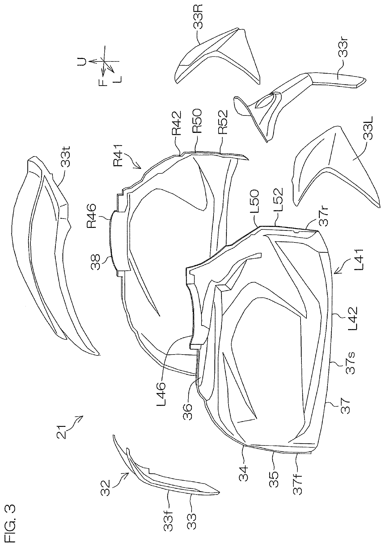
The patent describes a structure where the engine cover is divided into two pieces, each facing the engine. This allows for more flexibility in the shape of the engine cover. The two divided covers have connections that overlap the engine in a plan view. An exterior panel is placed outside the two divided covers to protect the connections. This prevents water from entering the engine cover and increases its waterproofness. Additionally, the exterior panel reduces the pressure on the boundaries between the two connections, increasing the durability of the connections.

Problems solved by technology

In order to increase the degree of shape freedom, it is conceivable that the top cowl of Japanese Patent Application Publication No. 2007-069823 will be divided into parts, and yet, if the top cowl is not divided at appropriate positions, it is impossible to effectively reduce all parts obtained by dividing the top cowl, and it is impossible to lighten restrictions imposed on the shapes or the like.
Likewise, when the top portion of Japanese Patent Application Publication No. 2018-192840 is divided into parts, it is impossible to lighten restrictions imposed on the shapes or the like if the top portion is not divided at appropriate positions.

Method used


Image

  • Outboard motor engine cover and outboard motor
  • Outboard motor engine cover and outboard motor
  • Outboard motor engine cover and outboard motor

Examples


Embodiment Construction

[0053]Preferred embodiments of the present invention will be hereinafter described in detail with reference to the accompanying drawings.

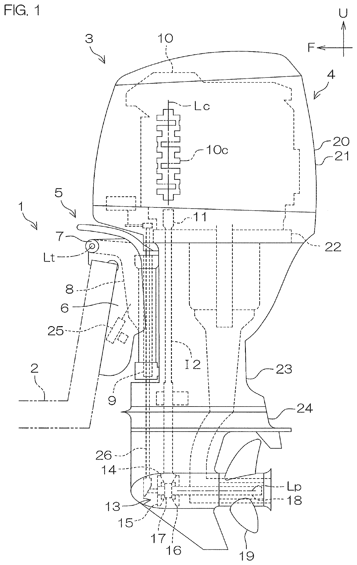
[0054]An outboard motor main body 4 in a basic posture will be hereinafter described. The basic posture is a posture in which a center line Lp of a propeller shaft 18 horizontally extends in a direction perpendicular to a center line Lt of a tilt shaft 7. A front-rear direction, an up-down direction, and a left-right direction are defined based on the outboard motor main body 4 being in the basic posture. The left-right direction corresponds to a width direction. The front-rear direction, the up-down direction, and the left-right direction of the outboard motor main body 4 correspond to the front-rear direction, the up-down direction, and the left-right direction of an engine cover 21, respectively. An “upper end” in the following description denotes a portion, which is positioned at the highest location, of an element. In other words, the “upper e...


PUM


Abstract

An outboard motor includes an engine to rotate a propeller and an engine cover that houses the engine. The engine cover includes two divided covers disposed above the engine and that directly face the engine. The two divided covers include two connections that are connected together and that overlap the engine in a plan view.

Description

CROSS REFERENCE TO RELATED APPLICATIONS[0001]This application claims the benefit of priority to Japanese Patent Application No. 2020-219305 filed on Dec. 28, 2020. The entire contents of this application are hereby incorporated herein by reference.BACKGROUND OF THE INVENTION1. Field of the Invention[0002]The present invention relates to an engine cover that is used for an outboard motor and that houses an engine, and relates to an outboard motor provided with the engine cover.2. Description of the Related Art[0003]An outboard motor provided with a cowling with which an engine is covered is disclosed by Japanese Patent Application Publication No. 2007-069823. An engine room in which the engine is disposed is formed by a top cowl and a bottom cowl of the cowling. FIG. 1 of Japanese Patent Application Publication No. 2007-069823 depicts the top cowl so as to be a single integrated member. FIG. 3 of Japanese Patent Application Publication No. 2007-069823 depicts the top cowl so as to di...

Claims


Application Information

Patent Timeline
IPC IPC(8): B63H20/32F02M35/10F02B61/04
CPCB63H20/32F02B61/045F02M35/10006F02M35/1015F02M35/167
Inventor HASEGAWA, HIROYUKIMATSUI, TAKAHIROHATA, RYOSUKE
Owner YAMAHA MOTOR CO LTD
Learn More