
Monitoring circuit and semiconductor device

a monitoring circuit and semiconductor technology, applied in the direction of logic circuits, semiconductor/solid-state device testing/measurement, instruments, etc., can solve the problems of inability to accurately monitor the semiconductor device, the accuracy of checking is not high, and the semiconductor device may not operate normally, etc., to achieve accurate and rapid recognition and accurate monitoring of the semiconductor devi

Active Publication Date: 2022-06-02
SK HYNIX INC
View PDF3 Cites 0 Cited by
  • Summary
  • Abstract
  • Description
  • Claims
  • Application Information

AI Technical Summary

Benefits of technology

The patent describes a monitoring circuit that can quickly and accurately detect defects in a semiconductor device. Additionally, the circuit can monitor the device in a digital way.

Problems solved by technology

A semiconductor device manufactured through semiconductor processing may not operate normally, or may have defects due to various factors.
Thus, defects of the semiconductor device are checked in the semiconductor processing, but the accuracy of checking is not high, and it takes a long time to check the semiconductor device.
In addition, heretofore according to existing checking methods, it is generally not practical to check defects of many semiconductor devices fabricated on a substrate one by one.

Method used


Image

  • Monitoring circuit and semiconductor device
  • Monitoring circuit and semiconductor device
  • Monitoring circuit and semiconductor device

Examples


Embodiment Construction

[0059]Hereinafter, embodiments of the disclosure will be described in detail with reference to the accompanying drawings.

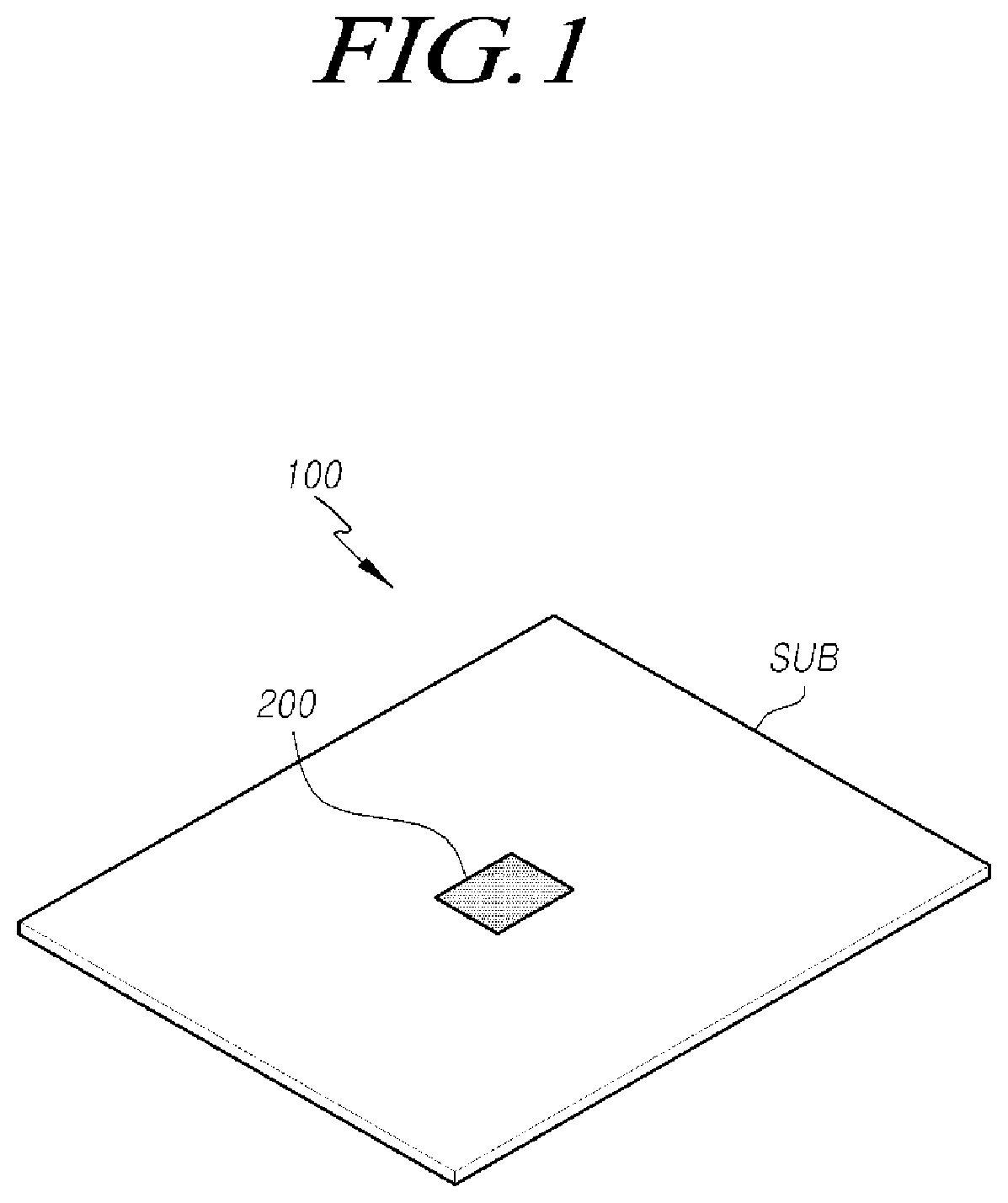
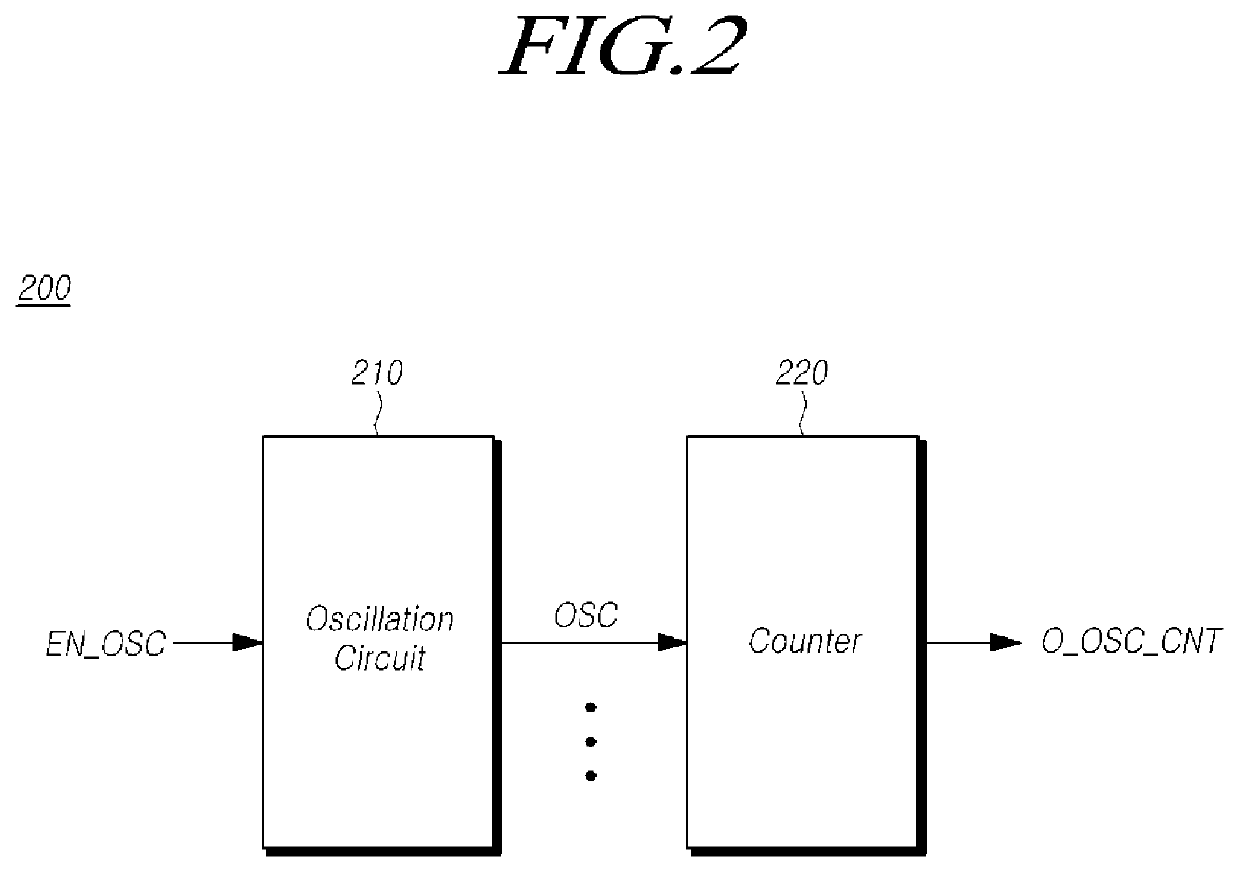
[0060]FIG. 1 is a diagram schematically illustrating a semiconductor device 100 including a monitoring device 200 according to an embodiment of the present disclosure. FIG. 2 illustrates a configuration of the monitoring circuit 200, according to an embodiment.

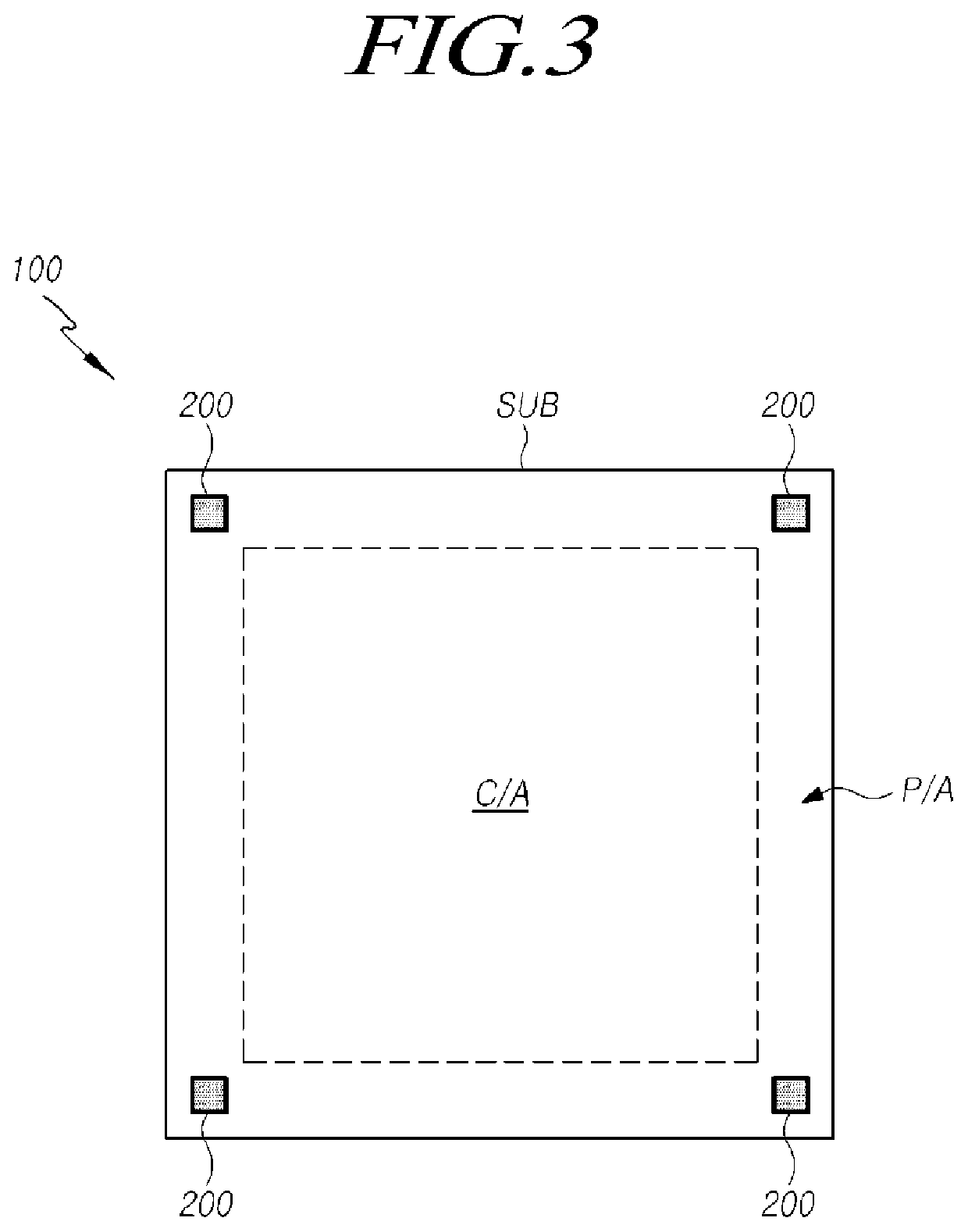
[0061]Referring now to FIGS. 1 and 2, the semiconductor device 100 may include at least one substrate (SUB), and the monitoring circuit 200 may be arranged on or in the at least one substrate (SUB). In an embodiment, the monitoring circuit 200 may be formed in the substrate (SUB) with the top surface of the monitoring circuit 200 being substantially coplanar with the top surface of the substrate (SUB). It is noted, however, that the invention is not limited based on the particular way by which the monitoring circuit 200 may be disposed on or in the substrate (SUB). The monitoring circuit 200 may be enabled a...


PUM


Abstract

Embodiments of the present disclosure relate to a monitoring circuit and a semiconductor device, and particularly, to a monitoring circuit including an oscillation circuit configured to generate an oscillation signal having a rising characteristic or a falling characteristic according to a threshold voltage level and a counter configured to count the number of rises or the number of falls of the oscillation signal, and a semiconductor device including the monitoring circuit.

Description

CROSS REFERENCE TO RELATED APPLICATION[0001]This application is a continuation of U.S. patent application Ser. No. 16 / 736,249 filed on Jan. 7, 2020, which claims priority under 35 U.S.C. 119(a) to Korean patent application number 10-2019-0083760 filed in the Korean intellectual property office on Jul. 11, 2019, which is incorporated herein by reference in its entirety.BACKGROUND OF THE INVENTION1. Field of the Invention[0002]Embodiments of the present disclosure relate to a monitoring circuit and a semiconductor device.2. Description of the Prior Art[0003]A semiconductor device manufactured through semiconductor processing may not operate normally, or may have defects due to various factors. Thus, defects of the semiconductor device are checked in the semiconductor processing, but the accuracy of checking is not high, and it takes a long time to check the semiconductor device. In addition, heretofore according to existing checking methods, it is generally not practical to check defe...

Claims


Application Information

Patent Timeline
Patent Type & Authority Applications(United States)
IPC IPC(8): G01R31/28H01L21/66
CPCG01R31/2884H03K19/20H01L22/34G01R31/2607G11C29/006G11C29/50
Inventor KIM, TAE-PYEONG
Owner SK HYNIX INC
Learn More