
Maintenance support system, maintenance support method, and program

a maintenance support and maintenance technology, applied in the field of maintenance support systems and maintenance support methods, can solve problems such as difficult immediate action, difficult to understand the status, and difficult to solve, and achieve the effect of preventing leakage of confidential information and few restrictions on imaging conditions

Pending Publication Date: 2022-05-26
SUMITOMO PRECISION PROD CO LTD
View PDF2 Cites 0 Cited by
  • Summary
  • Abstract
  • Description
  • Claims
  • Application Information

AI Technical Summary

Benefits of technology

The invention helps prevent sensitive information from leaks and requires minimal restrictions on taking images.

Problems solved by technology

In the case of the above-described action by telephone, since the communication is verbal communication, there is a case in which the status of the trouble may not be well communicated to the maintenance supporter, or the instruction of the maintenance supporter may not be well communicated to the maintenance worker, resulting in that the trouble cannot be solved.
Although, the maintenance worker may send an obtained picture data of the maintenance target to the maintenance supporter by e-mail, etc., as needed, and the maintenance supporter checks the picture data to grasp the status of the trouble, a problem exists in that understanding the status takes time.
Further, in the case of the above-described action in which a skilled worker is dispatched, a problem exists in that taking immediate action is difficult.
However, in the above-described maintenance support system, if the captured image is transmitted as it is to the support terminal, there is a risk that the captured image includes confidential information of the installation site.
If the captured image including the confidential information is transmitted to the maintenance supporter side, the maintenance supporter can know the confidential information, thus causing a problem.

Method used


Image

  • Maintenance support system, maintenance support method, and program
  • Maintenance support system, maintenance support method, and program
  • Maintenance support system, maintenance support method, and program

Examples


Embodiment Construction

[0057]Hereinafter, a maintenance support system according to an embodiment of the present invention will be described with reference to the appended drawings.

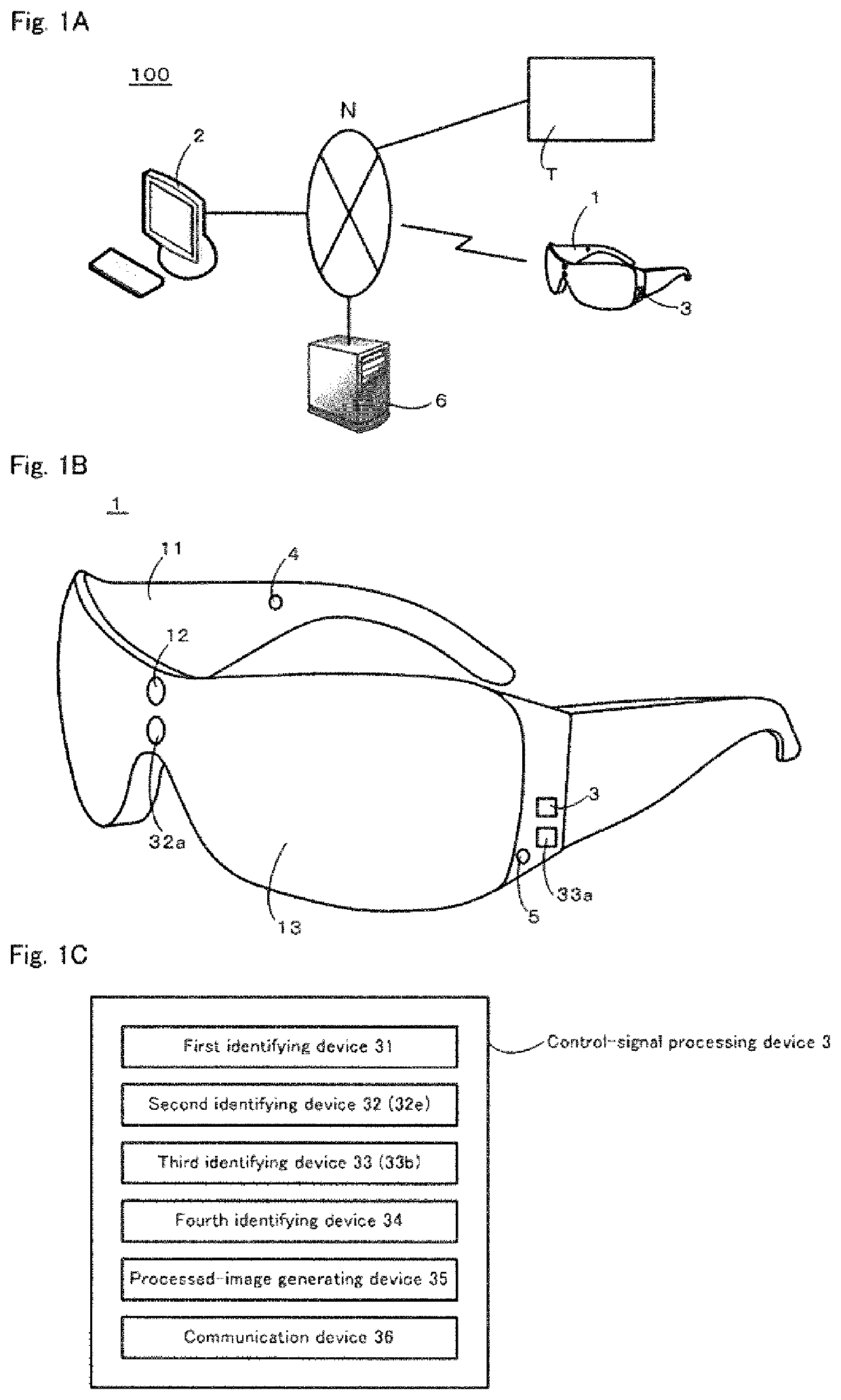
[0058]FIGS. 1A to 1C are diagrams to schematically show an outline configuration of a maintenance support system according to the present embodiment. FIG. 1A is a general configuration diagram, FIG. 1B is a diagram showing a wearable terminal and components attached thereto, and FIG. 1C is a block diagram showing the internal structure of a control-signal processing device shown in FIG. 1B.

[0059]As shown in FIG. 1A, a maintenance support system 100 according to the present embodiment includes a wearable terminal 1, a support terminal 2, and a control-signal processing device 3.

[0060]The wearable terminal 1 is a terminal worn by a maintenance worker who performs maintenance work at the installation site of a maintenance target (industrial equipment such as a substrate processing apparatus, and the like).

[0061]As shown in FIG. 1B...


PUM


Abstract

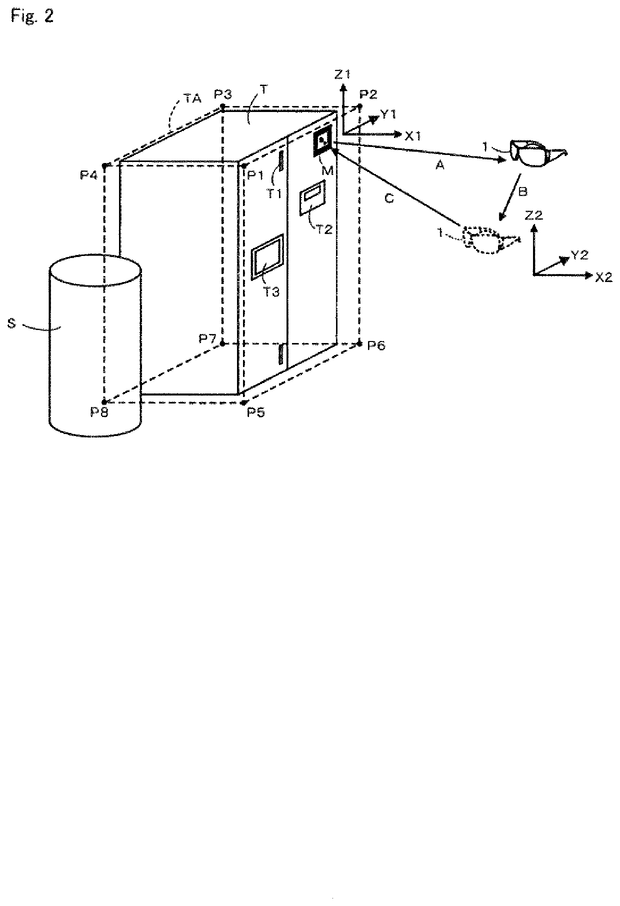
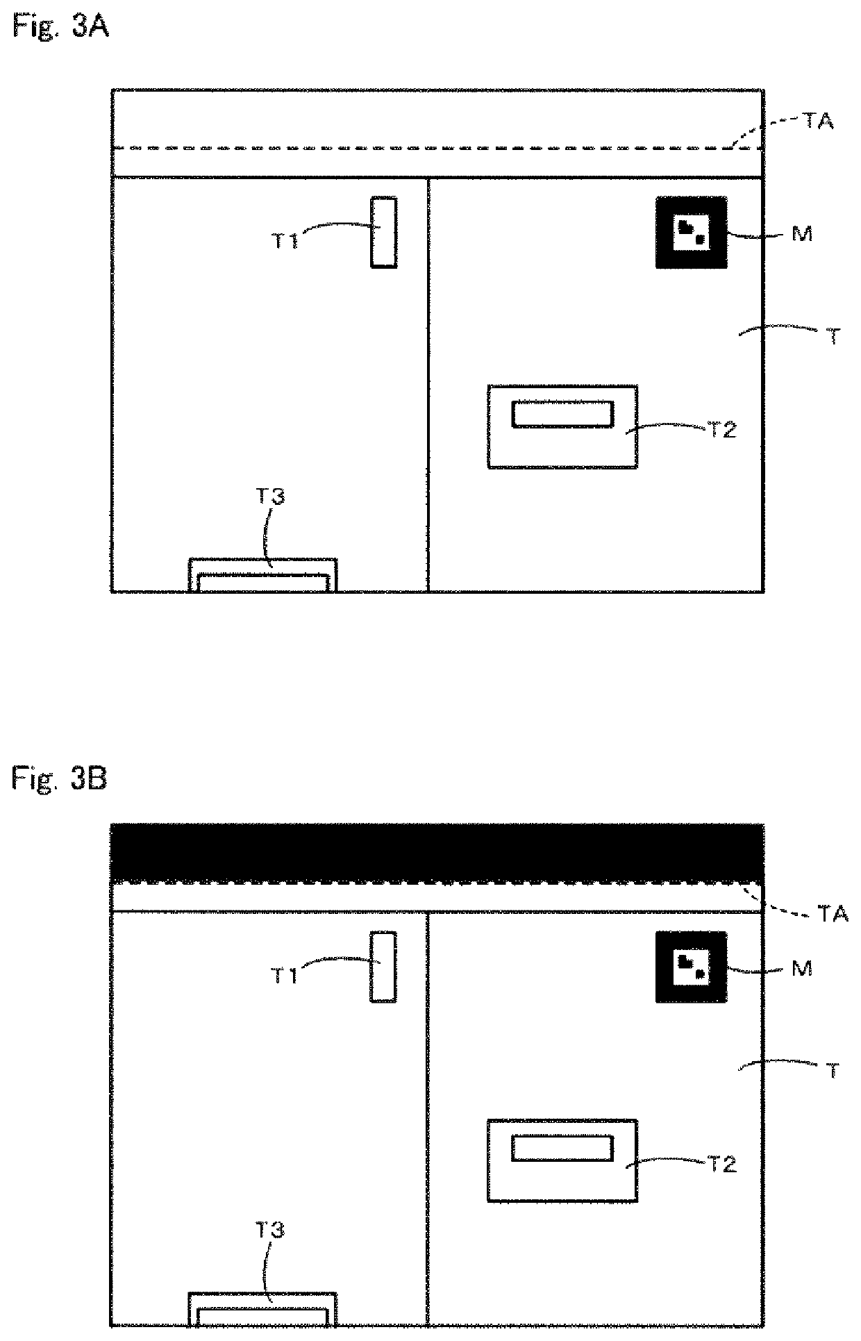
A maintenance support system includes a terminal including an imaging device, a device configured to identify a three-dimensional area TA including a maintenance target T with reference to a predetermined reference point, a device for identifying a position (vector A) of the imaging device in an initial state with respect to the reference point, a device for identifying a change of position (vector B) from the initial state of the imaging device, a device for identifying a position (vector C) of the reference point with reference to the imaging device in a post-movement state in which the terminal has moved, and identifying a pixel area corresponding to the three-dimensional area in a captured image, and a device for generating a processed image in which a portion other than the pixel area is made invisible. A communication device is provided for transmitting the processed image to a support terminal.

Description

TECHNICAL FIELD[0001]The present invention relates to a maintenance support system, a maintenance support method, and a program for supporting maintenance work of a maintenance target such as industrial equipment. In particular, the present invention relates to a maintenance support system, a maintenance support method, and a program, which can prevent leakage of confidential information etc. excluding the maintenance target, and in which there are few restrictions on imaging conditions.BACKGROUND ART[0002]Conventionally, when a trouble occurs in industrial equipment such as a substrate processing apparatus, action taken generally in response thereto is such as follows: a maintenance worker who is at the installation site of the industrial equipment which is the maintenance target confirms the status of the trouble and then reports the status of the trouble by telephone to a maintenance supporter of the manufacturer of the maintenance target, and the maintenance supporter gives vari...

Claims


Application Information

Patent Timeline
IPC IPC(8): G06V10/22G06T7/70G06T11/00G06Q10/00
CPCG06V10/225G06T7/70G06T2207/30204G06Q10/20G06T2207/10028G06T11/00G06T19/00H04N7/183G06T1/0007H04N7/147G06T7/246G06T7/55G06T2207/10016G06T2207/10024G06V10/22G06V10/25G06F1/163G02B27/017
Inventor TOMINAGA, YUTAKAHABE, TAKESHITSUJIOKA, NORIHIRO
Owner SUMITOMO PRECISION PROD CO LTD
Learn More