Sealing method for server

a server and sealing method technology, applied in the direction of electrical apparatus, electrical apparatus, electrical apparatus contruction details, etc., can solve the problem that the general sealing method does not allow the case of a cooling system

Active Publication Date: 2022-05-19
INVENTEC PUDONG TECH CORPOARTION +1
View PDF10 Cites 0 Cited by
  • Summary
  • Abstract
  • Description
  • Claims
  • Application Information

AI Technical Summary

Benefits of technology

[0016]According to the above description, in the present disclosure, by coating the first colloid and the second colloid, the gap between the frame and the component can be filled, therefore forming a gas tightness wall between the two openings. The gas tightness wall can provide gas tightness while maintaining the connection of the component. Fixing the frame contain the gas tightness wall on the housing and filled the gap with fills material, maintaining the gas tightness of the housing and letting the components connect inside and outside of the housing.

Problems solved by technology

A general sealing method does not allow the case of a cooling system to achieve gas tightness and have an electronic connection at the same time.

Method used


Image

  • Sealing method for server
  • Sealing method for server
  • Sealing method for server

Examples


Embodiment Construction

[0026]Reference will now be made in detail to the present embodiments of the invention, examples of which are illustrated in the accompanying drawings. Wherever possible, the same reference numbers are used in the drawings and the description to refer to the same or like parts.

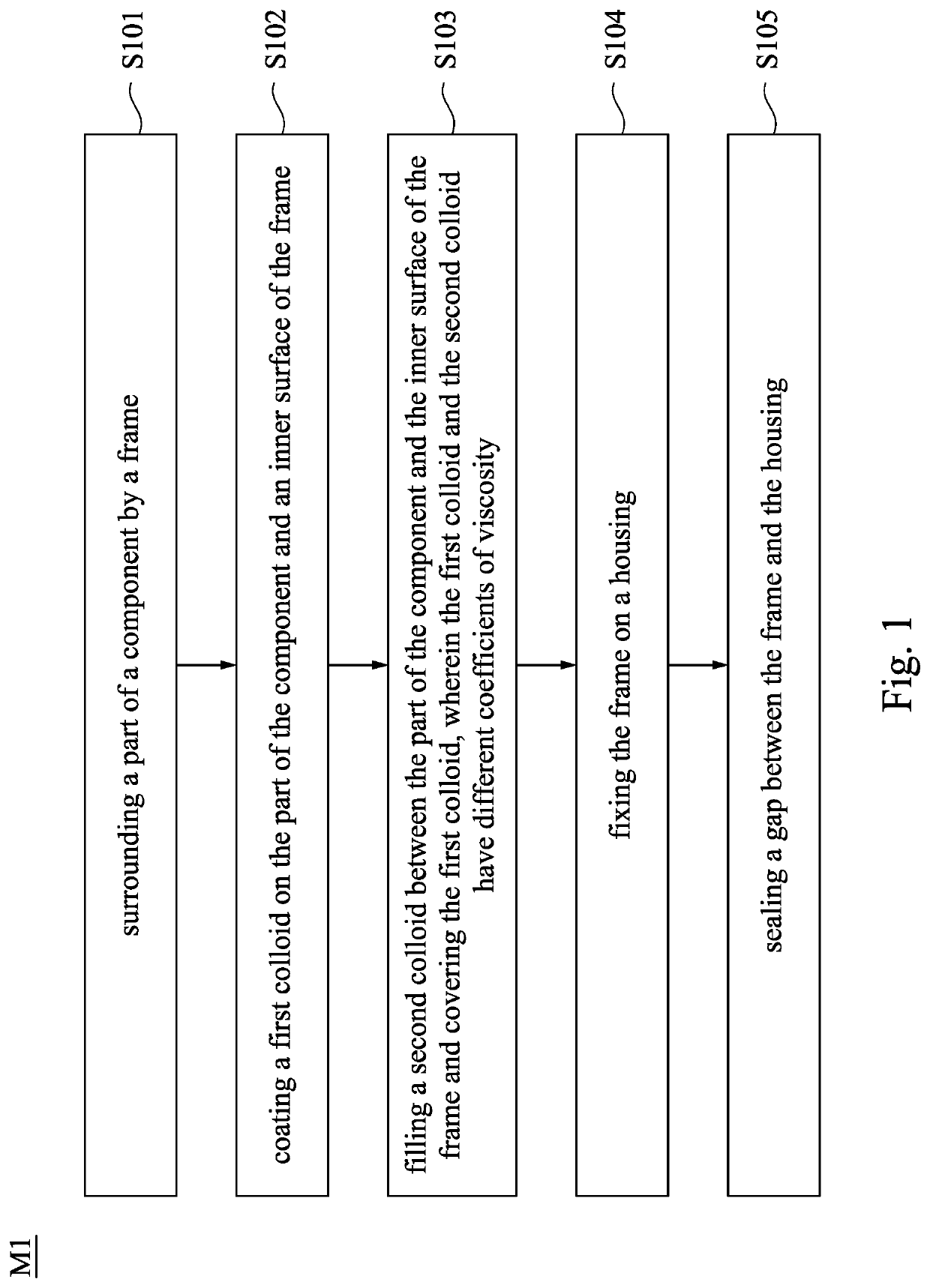
[0027]Reference is made to FIG. 1. FIG. 1 is a flowchart of the sealing method of a server, according to one embodiment of this invention. The sealing method of a server M1 mainly contains step S101 to step S105.

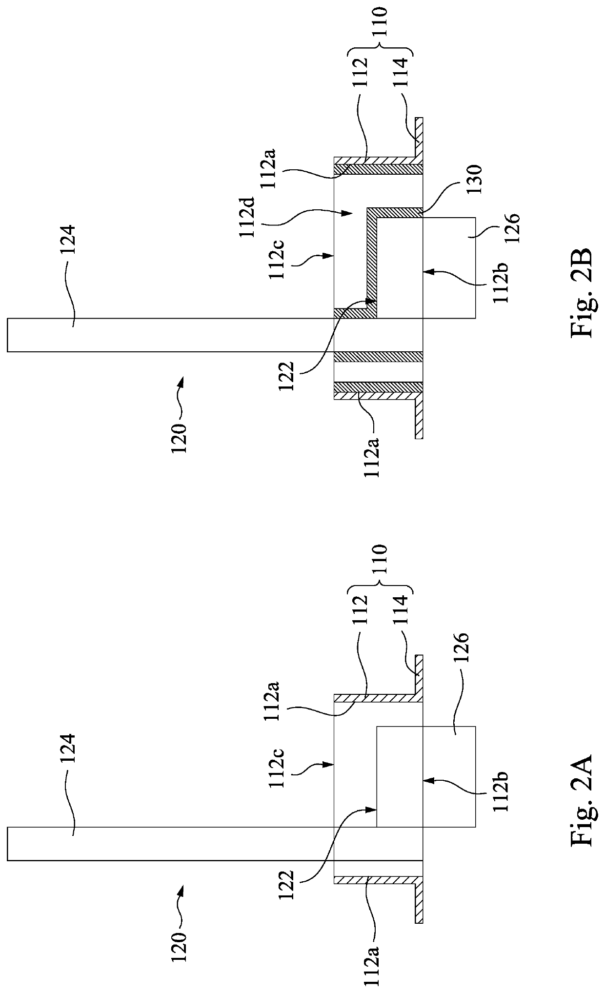
[0028]In step S101, frame 110 surrounds a part 122 of a component 120. Reference is made to FIG. 2A. FIG. 2A is a cross-sectional view of one of the stages of a sealing method of a server, according to one embodiment of this invention. As shown in FIG. 2A, body 112 of the frame 110 has an inner surface 112a, a first opening 112b and a second opening 112c. The first opening 112b and the second opening 112c are connected. In some embodiments, the first opening 112b and the second opening 112c have a squa...


PUM


Abstract

A sealing method for a server includes: surrounding a part of a component by a frame; coating a first colloid on the part of the component and an inner surface of the frame; filling a second colloid between the part of the component and the inner surface of the frame and covering the first colloid, in which the first colloid and the second colloid have different coefficients of viscosity; fixing the frame on a housing; and sealing a gap between the frame and the housing.

Description

CROSS-REFERENCE TO RELATED APPLICATION[0001]This application claims priority to China Application Serial Number 202011297196.7 filed Nov. 18, 2020, which is herein incorporated by reference in its entirety.BACKGROUNDField of Invention[0002]The present invention relates to a sealing method for a server.Description of Related Art[0003]A two phase immersion cooling system is typically used to cool down and keep electronic systems (e.g. servers). The phase transition between the gas and liquid of the dielectric fluid inside the cooling system can improve the heat dissipation efficiency of the electronic systems that keep in thereof. This type of cooling system can also prevent the error of electronic systems that may be caused by the contact of air or dust.[0004]To reduce the leakage of the dielectric fluid inside the cooling system, the case of thereof needs to provide gas tightness. However, the electronic systems have to pass through the case of the cooling system to make electronic ...

Claims


Application Information

Patent Timeline
Patent Type & Authority Applications(United States)
IPC IPC(8): H05K5/06
CPCH05K5/06H05K5/062H05K7/203H05K5/069H05K7/20818
Inventor TUNG, KAI-YANGCHEN, HUNG-JU
Owner INVENTEC PUDONG TECH CORPOARTION
Why Eureka
Try Eureka