
Battery system, method for diagnosing a battery system, and motor vehicle

a battery system and battery technology, applied in the field of battery systems, can solve the problems of voltage divider distortion and change the expected measured voltage, and achieve the effects of robust contactor-opening, improved diagnostic coverage, and checking the plausibility of switching state monitoring

Pending Publication Date: 2022-05-19
ROBERT BOSCH GMBH
View PDF0 Cites 2 Cited by
  • Summary
  • Abstract
  • Description
  • Claims
  • Application Information

AI Technical Summary

Benefits of technology

The invention is a battery system for electric vehicles that is isolated from other low-voltage networks, allowing for voltage measurements without interference. The system can diagnose switches and detect potential defects using a reference potential that is independent of voltage levels or fluctuations. The method utilizes the full potential of the circuit and can detect faults in the battery switch-off device and other components.

Problems solved by technology

On the other hand, the distortion of the voltage divider changes the expected measured voltage.

Method used


Image

  • Battery system, method for diagnosing a battery system, and motor vehicle
  • Battery system, method for diagnosing a battery system, and motor vehicle
  • Battery system, method for diagnosing a battery system, and motor vehicle

Examples


first embodiment

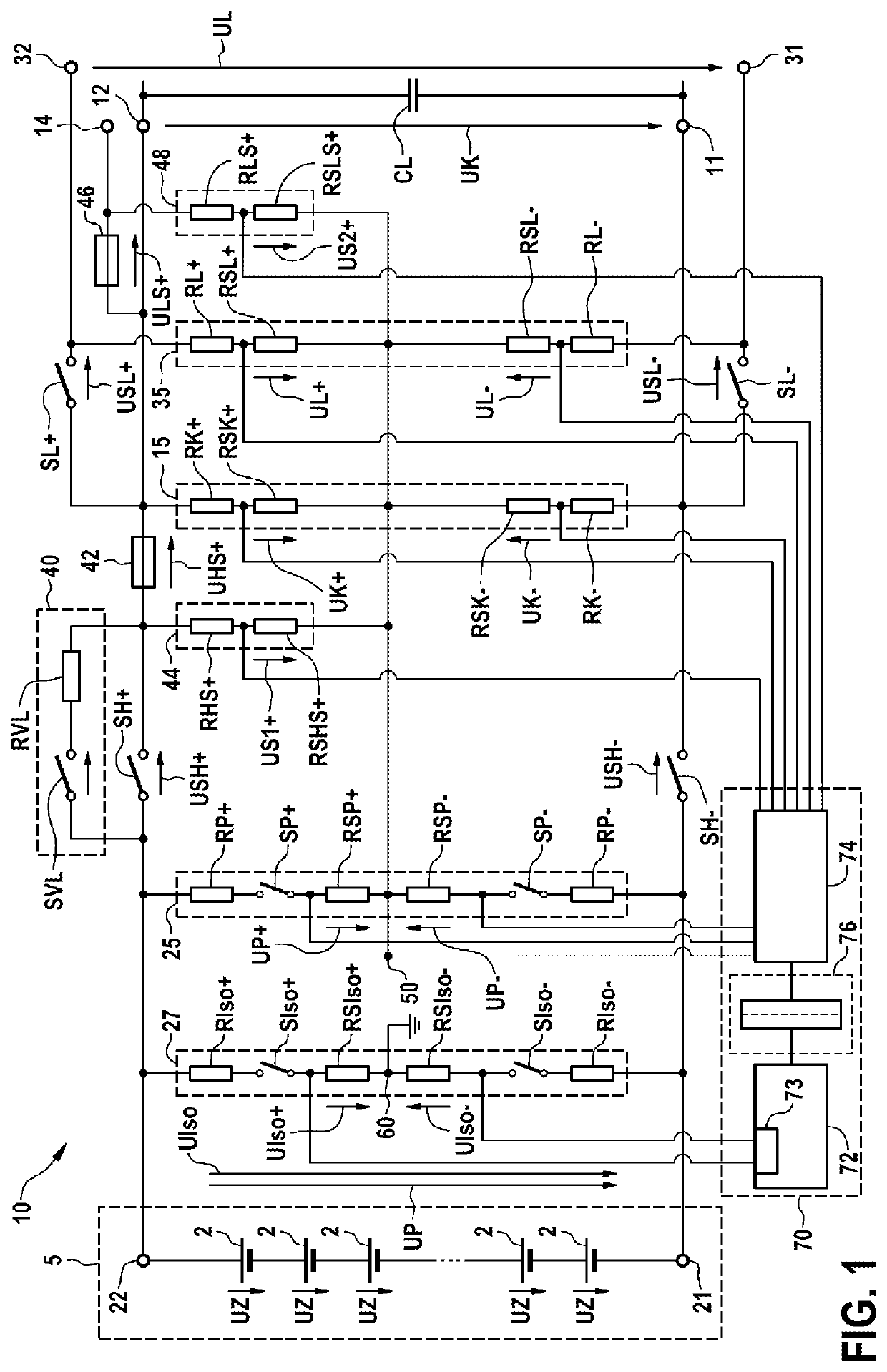
[0106]FIG. 1 shows a schematic illustration of a battery system 10 proposed according to the invention.

[0107]In this case, the battery system 10 comprises a battery pack 5 that has a negative pole 21, a positive pole 22 and a plurality of battery cells 2 connected in series with one another, each having a cell voltage UZ, and a pack voltage divider 25.

[0108]The battery system 10 furthermore comprises a coupling network that has a first negative terminal 11 and a first positive terminal 12, and a coupling voltage divider 15. In this case, the first positive terminal 12 is able to be connected to the positive pole 22 by way of a positive main switch SH+ and the first negative terminal 11 is able to be connected to the negative pole 21 by way of a negative main switch SH−. The main switches SH+, SH− are designed for example in the form of electromechanical relays or contactors.

[0109]The pack voltage divider 25 in this case has a positive pack measurement resistor RP+ and a positive sub...

second embodiment

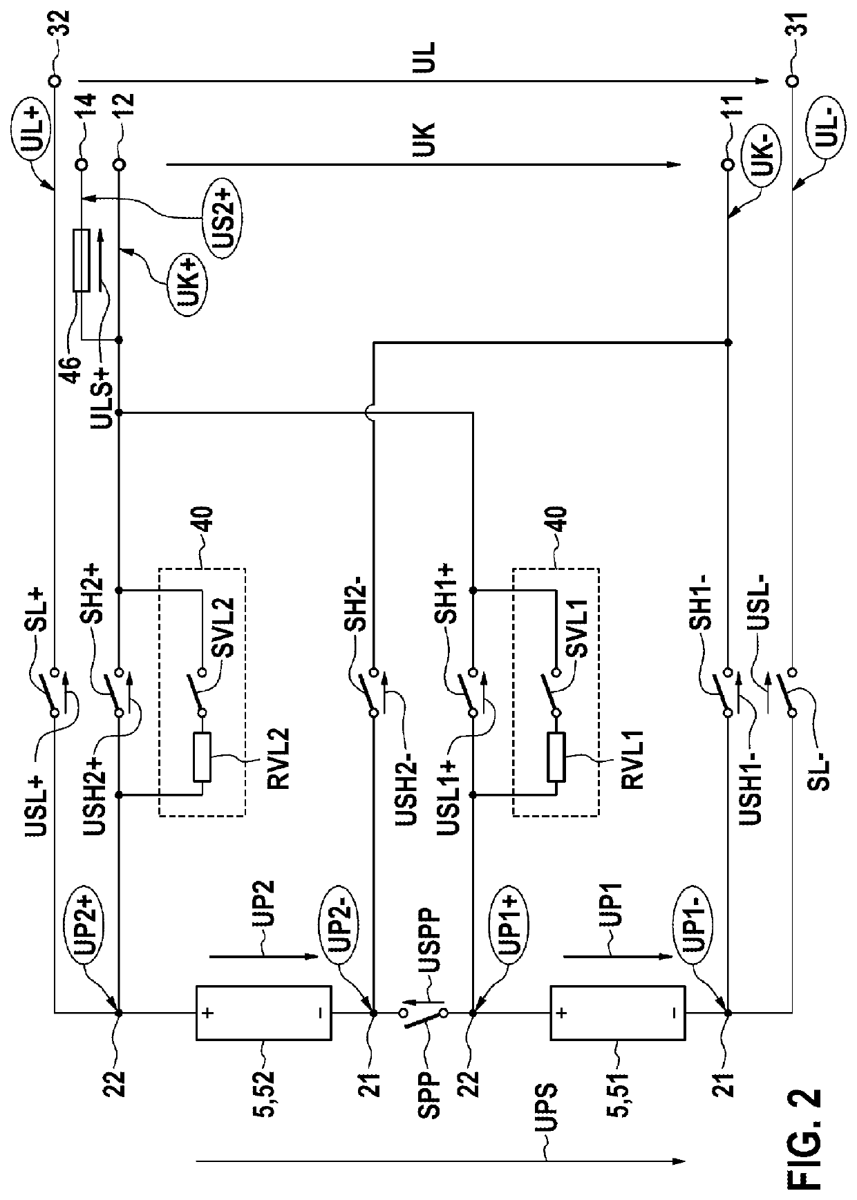
[0137]The method proposed according to the invention may be expanded or adapted for the battery system 10 proposed according to the invention in FIG. 2.

[0138]FIG. 2 schematically shows that a first positive pack measured voltage UP1+, a first negative pack measured voltage UP1−, a second positive pack measured voltage UP2+, a second negative pack measured voltage UP2−, a positive coupling measured voltage UK+, a negative coupling measured voltage UK−, a positive charging measured voltage UL+, a negative charging measured voltage UL- and a second positive auxiliary measured voltage US2+ are measured.

[0139]The following table illustrates the calculation of the pack voltages UP1, UP2 of the respective battery packs 51, 52, of the overall pack voltage UPS, of the voltages USH1+, USH2+, USH1−, USH2−, USL+, USL−, USPP dropped across the respective switches SH1+, SH2+, SH1−, SH2−, SL+, SL−, SPP, of the voltage ULS+ dropped across the positive charging fuse 46, of the coupling voltage UK an...


PUM

PropertyMeasurementUnit
output voltageaaaaaaaaaa
voltageaaaaaaaaaa
voltageaaaaaaaaaa

Abstract

A battery system having a battery pack with a negative pole, a positive pole and a battery cell, a coupling network having a first negative terminal and a first positive terminal, a pack voltage divider, and a coupling voltage divider. The first positive terminal is connectable to the positive pole via a switch. Optionally, the first negative terminal is connectable to the negative pole via a switch. The pack voltage divider includes a two resistors connected between the positive pole and a first reference point. A negative pack measurement resistor and a negative sub-pack measurement resistor are dis-connectable from the negative pole or the first reference point via a switch. A positive coupling measurement resistor and a positive sub-coupling measurement resistor are connected between the first positive terminal and the first reference point. Two resistors are connected between the first negative terminal and the first reference point.

Description

BACKGROUND OF THE INVENTION[0001]The invention relates to a battery system comprising at least one battery pack that has a negative pole, a positive pole and at least one battery cell, at least one coupling network that has a first negative terminal and a first positive terminal, a pack voltage divider and a coupling voltage divider, wherein the first positive terminal is able to be connected to the positive pole by way of a positive main switch and / or the first negative terminal is able to be connected to the negative pole by way of a negative main switch, wherein the pack voltage divider comprises a positive pack measurement resistor and a positive sub-pack measurement resistor that are connected in series with one another between the positive pole and a first reference point and are able to be disconnected from the positive pole or the first reference point by way of a positive pack measurement switch, and a negative pack measurement resistor and a negative sub-pack measurement r...

Claims


Application Information

Patent Timeline
Patent Type & Authority Applications(United States)
IPC IPC(8): H01M50/569H02J7/00G01R31/382G01R31/371H01M10/48
CPCH01M50/569H02J7/0047H01M2220/20G01R31/371H01M10/482G01R31/382H02J7/0045G01R31/396H02H7/18B60L58/10G01R15/04B60L58/00H01M10/425H01M2200/103G01R31/3835G01R27/025G01R31/74G01R31/3277B60L3/0038
Inventor KRIEG, BERENGARTZIVANOPOULOS, CHRYSANTHOSSWOBODA, JOHANNESSCHAEDLICH, THOMAS
Owner ROBERT BOSCH GMBH
Learn More