
System and method for customized visualization of the surroundings of self-propelled work vehicles

a work vehicle and environment technology, applied in vehicle position/course/altitude control, process and machine control, instruments, etc., can solve the problems of limited view of the surroundings of the work vehicle, increased difficulty, and limited operator's view, so as to achieve a simple and intuitive way of manipulating the display

Active Publication Date: 2022-05-19
DEERE & CO
View PDF5 Cites 0 Cited by
  • Summary
  • Abstract
  • Description
  • Claims
  • Application Information

AI Technical Summary

Benefits of technology

The invention introduces a system and method for using gestures on a touch screen to manipulate images and a way to automatically change the region of interest of a camera based on work conditions. This makes the user experience more convenient and intuitive.

Problems solved by technology

One problem for the operator is that the surroundings of the work vehicle can only be directly observed to a limited extent from the operator cab.
There is an added difficulty in the case of, e.g., front loader and rear loader work machines, wherein the operator's view may be substantially limited to the front or rear depending on the orientation and position of the work implement(s).
Consequently, the operator may be unable to sufficiently identify external objects from a typical working position that are concealed by the work implement in his field of vision.
These systems can help an operator to see what is around the vehicle, but they require individual selection of a given image, and are limited in scope to the particular images captured by cameras at predetermined locations on the work vehicle.
This can be problematic for contexts in which it is desirable for an operator to view smaller sections of the full surround (i.e., 360-degree) view, or to manipulate the shape and size of the image.

Method used


Image

  • System and method for customized visualization of the surroundings of self-propelled work vehicles
  • System and method for customized visualization of the surroundings of self-propelled work vehicles
  • System and method for customized visualization of the surroundings of self-propelled work vehicles

Examples


Embodiment Construction

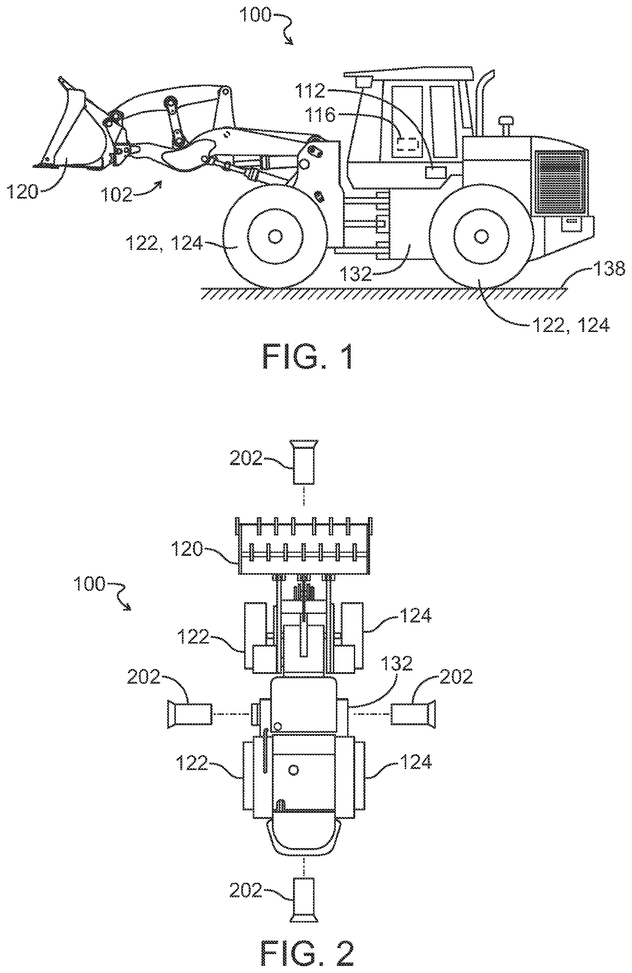
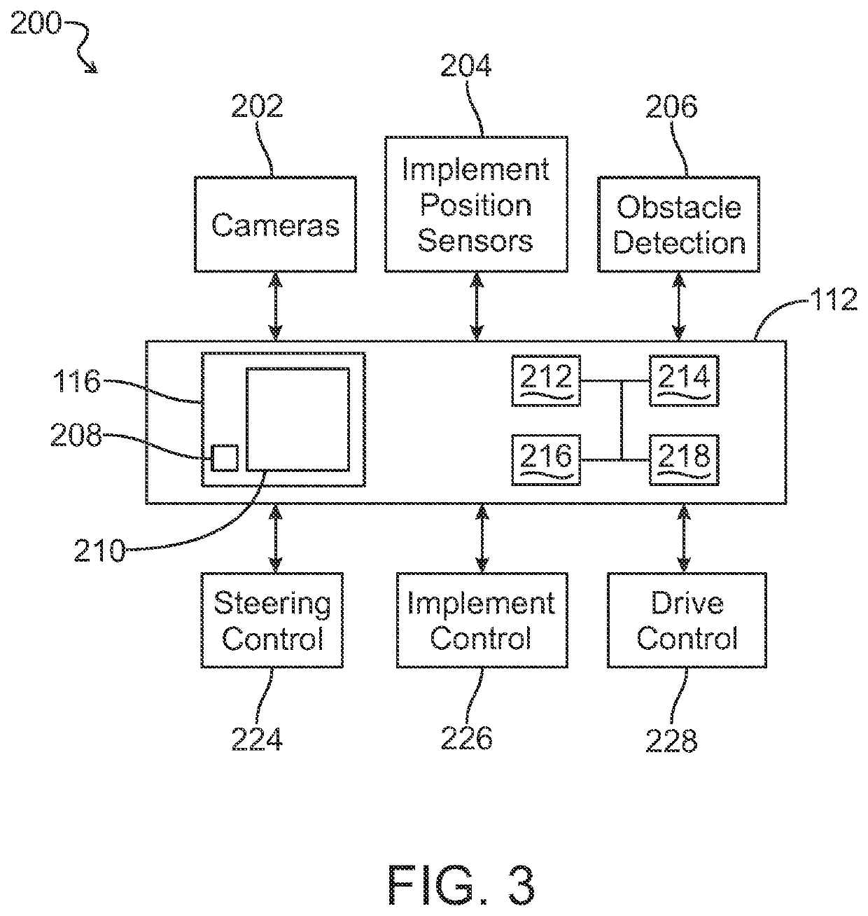
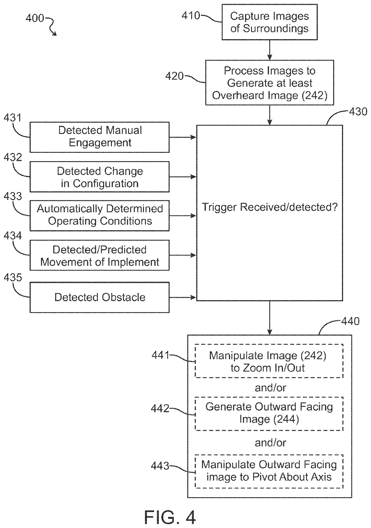
[0037]Referring now to FIGS. 1-8C, various embodiments may now be described of a system and method for customized visualization of the surroundings of a self-propelled work vehicle.

[0038]FIG. 1 in a particular embodiment as disclosed herein shows a representative self-propelled work vehicle 100 in the form of, for example, a loader having a front-mounted working implement 120 for modifying the proximate terrain. It is within the scope of the present disclosure that the work vehicle 100 may be in the form of any other self-propelled vehicle using an attachment implement to modify the proximate terrain, particularly a work vehicle designed for use in off-highway environments such as a construction or forestry vehicle, for example.

[0039]The illustrated work vehicle 100 includes a main frame 132 supported by a left-side tracked ground engaging unit 122 and a right-side tracked ground engaging unit 124, and at least one travel motor (not shown) for driving the respective ground engaging ...


PUM


Abstract

A self-propelled work vehicle is provided with a control system enabling the use of gestures on a touch screen interface to provide a simple and intuitive way to manipulate displayed images, and / or automatically changing a region of interest of a surround view camera unit. Exemplary automatic manipulation may be implemented if a work vehicle is detected as performing a certain function, wherein surround view images can automatically change to a smaller sub-view which gives more focused visibility appropriate to that function. The distortion and simulated field of view of surround view images may also / otherwise be automatically manipulated based on a detected operation / function. The control system can also / otherwise dynamically modify surround view images in accordance with a detected work state, and / or based on outputs from an obstacle detection system. The control system can also / otherwise lock the sub-view to recognized objects of interest, such as trucks or trenches.

Description

FIELD OF THE DISCLOSURE[0001]The present disclosure relates generally to self-propelled work vehicles such as construction and forestry machines, and more particularly to systems and methods for customized visualization of the surroundings for such self-propelled work vehicles.BACKGROUND[0002]Self-propelled work vehicles as discussed herein may for example include excavator machines, loaders, forestry machines, and other equipment which modify the terrain or equivalent working environment in some way. These work vehicles may have tracked or wheeled ground engaging units supporting the undercarriage from the ground surface, and may further include one or more working implements which are used to modify the terrain in coordination with movement of the work vehicle.[0003]There is an ongoing need in the field of such work vehicles for solutions that provide better operational awareness for the operator. One problem for the operator is that the surroundings of the work vehicle can only b...

Claims


Application Information

Patent Timeline
IPC IPC(8): E02F9/20E02F9/26G05D1/02
CPCE02F9/205E02F9/265G05D2201/0202G05D1/0238G05D1/0246B60R1/00B60R2300/10B60R2300/306B60R2300/30E02F9/261
Inventor BRUFLODT, RACHELKEAN, MICHAEL G.LENSING, KEITH J.WUISAN, GIOVANNI A.
Owner DEERE & CO
Learn More