
Method for ascertaining a variable characterizing a flow rate of a fuel injector

Active Publication Date: 2022-05-12
ROBERT BOSCH GMBH
View PDF5 Cites 2 Cited by
  • Summary
  • Abstract
  • Description
  • Claims
  • Application Information

AI Technical Summary

Benefits of technology

This patent describes a method for using machine learning to map complex interactions of multiple model parameters in a closed data model. This model can be integrated into an engine control unit and used to recognize and predict degradation in the system. By combining different approaches and methods, the system can achieve greater accuracy and robustness in identifying degradation. The method is based on purely scalar injection system variables and can provide necessary data for model training by performing parameter variations and measuring the injection system separately from the engine. The method can be implemented as a computer program and provides low-cost solutions, particularly when an operational control unit is already present.

Problems solved by technology

Even when fuel filters are used in such a fuel supply system, deposits or other contaminations may still occur at the openings of the injectors, whether as a result of particles or substances not filtered out of the fuel or else as a result of coking.
In spite of the advances achieved with such functions, the determination of the coking remains a challenge.
Interactions with other tolerances as well as ambient influences hamper the determination of the coking to the accuracy required, so that it is not always possible to utilize the full functional scope of these functions.
Errors in methods in which a correction of the activation parameter of the fuel injector is carried out based on the closing point in time of the nozzle needle generally correlate one to one with errors of the injection quantity.
In this case, each individual method or each individual approach, considered individually, usually has specific weaknesses, which means that the required accuracy and robustness of the recognition of the degradation is not achieved.
Bundling and combining the different model approaches for this purpose in one data model now results in the specific weakness of the various approaches carrying less weight, and thus a more accurate ascertainment of the coking is possible.
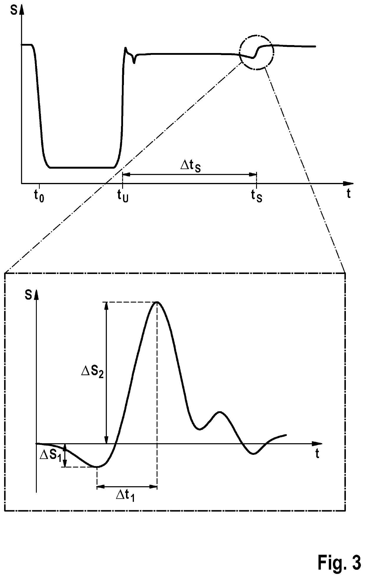
One weakness of this approach is that the needle closing duration is not solely a function of the coking of the injector but also a function of a guide clearance of the nozzle needle.
The guide clearance is not constant, however, and may change over time as a function of the load, i.e., it “drifts.” This drift of the guide clearance is an unknown which, in addition to other disturbances, distorts the coking model of this approach.

Method used


Image

  • Method for ascertaining a variable characterizing a flow rate of a fuel injector
  • Method for ascertaining a variable characterizing a flow rate of a fuel injector
  • Method for ascertaining a variable characterizing a flow rate of a fuel injector

Examples


Embodiment Construction

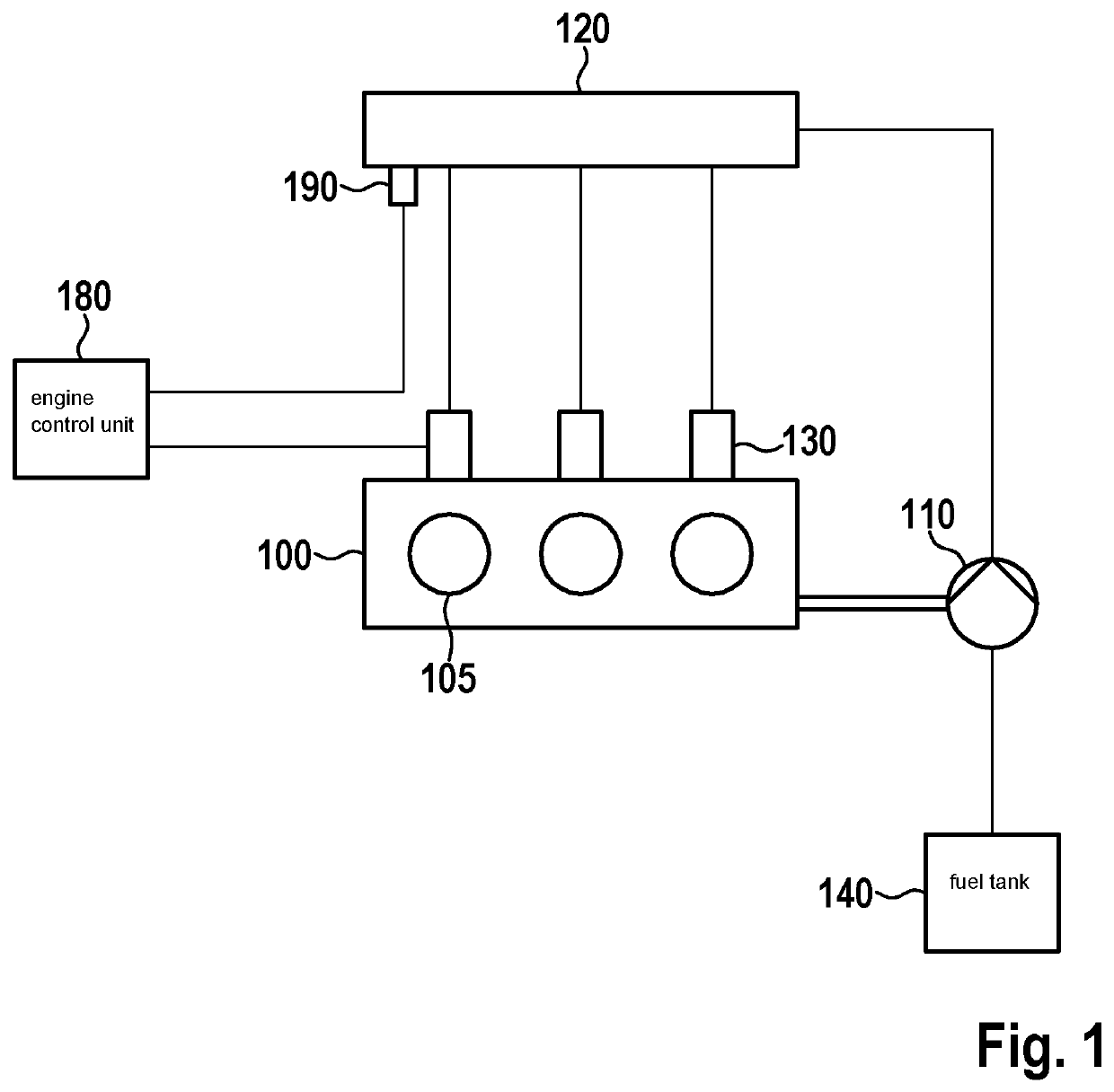
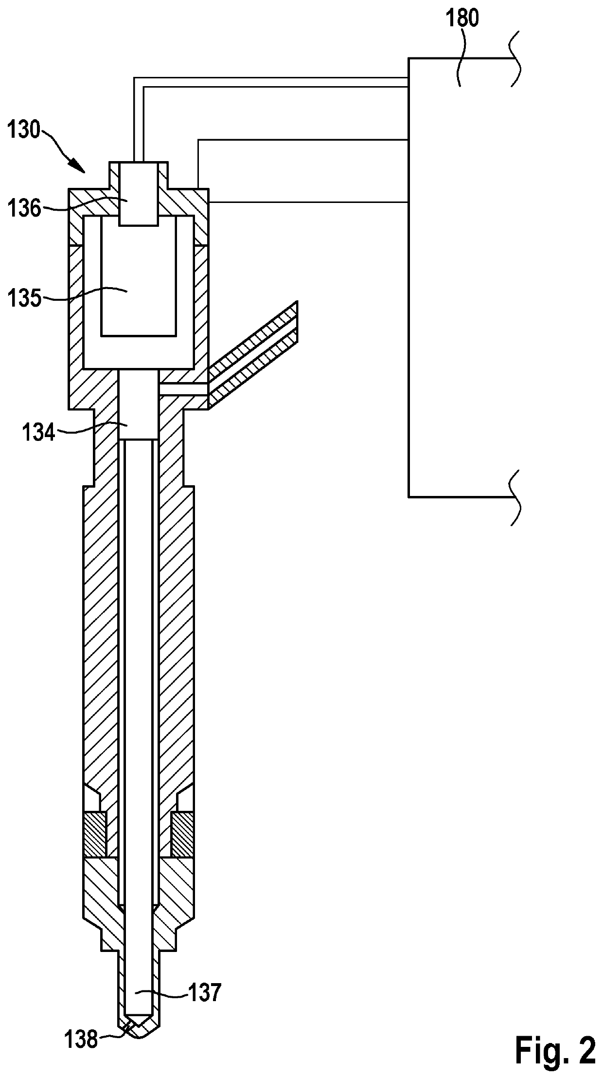
[0036]An internal combustion engine 100 is schematically shown in FIG. 1, which is suitable for carrying out a method according to the present invention. Internal combustion engine 100 includes, for example, three combustion chambers and associated cylinders 105. Each combustion chamber 105 is assigned a fuel injector 130, each of which, in turn, is connected to a high pressure accumulator 120, a so-called rail, via which it is supplied with fuel. It is understood that a method according to the present invention may also be carried out in an internal combustion engine including an arbitrary number of cylinders, for example, four, six, eight or twelve cylinders. It is also understood that a method according to the present invention may also be carried out in an internal combustion engine that includes more than one rail, for example, V-engines including two rails.

[0037]Furthermore, high pressure accumulator 120 is fed fuel from a fuel tank 140 via a high pressure pump 110. High press...


PUM


Abstract

A method for ascertaining a variable characterizing a flow rate of a fuel injector during an operation of an internal combustion engine, to which the fuel injector is assigned. At least two input values for a data-based model are ascertained, and at least one output value is determined with the aid of the data-based model, on the basis of which a value for the variable characterizing the flow rate of the fuel injector is ascertained. The data-based model combines at least two methods differing from one another for ascertaining a variable characterizing a flow rate of a fuel injector.

Description

FIELD[0001]The present invention relates to a method for ascertaining a variable characterizing a flow rate of a fuel injector, in particular, a coking, during an operation of an internal combustion engine, to which the fuel injector is assigned, as well as to a processing unit and to a computer program for carrying out the method.BACKGROUND INFORMATION[0002]For modern internal combustion engines, a fuel supply system may be used, in which fuel is stored at a relatively high pressure in a high pressure accumulator, in a so-called rail, which is then fed to individual fuel injectors and introduced from these in a targeted manner into combustion chambers of the internal combustion engine. Even when fuel filters are used in such a fuel supply system, deposits or other contaminations may still occur at the openings of the injectors, whether as a result of particles or substances not filtered out of the fuel or else as a result of coking.SUMMARY[0003]According to the present invention, a...

Claims


Application Information

Patent Timeline
IPC IPC(8): F02M65/00G05B13/02
CPCF02M65/00G05B13/027F02D41/38F02D41/1405F02D41/1401F02D2041/389F02D2041/1433F02M65/001F02D41/2467F02M65/003F02M65/006F02D2041/1436F02D41/247
Inventor BOLLINGER, STEFANNONNENMACHER, STEFANHEITZ, DANIELIRAN, GABRIELBUCHER, KILIANKUTTER, MICHAELTHUM, PATRICK
Owner ROBERT BOSCH GMBH
Learn More