A fluid handling structure and method for a gas phase deposition apparatus

Pending Publication Date: 2022-05-12
NEDERLANDSE ORG VOOR TOEGEPAST-NATUURWETENSCHAPPELIJK ONDERZOEK (TNO)
View PDF0 Cites 0 Cited by
  • Summary
  • Abstract
  • Description
  • Claims
  • Application Information

AI Technical Summary

Benefits of technology

The patent aims to provide a fluid handling structure that can ensure a uniform flow of fluid throughout a gas phase deposition cycle. Specifically, the invention proposes arranging two elongated slits in a way that they are positioned one after another, transverse to their length direction. This arrangement improves the gas phase deposition while keeping a consistent flow distribution over the slits. This results in improved performance and efficiency of the fluid handling structure.

Problems solved by technology

However, it is experienced that typically for large widths, slit widths variations due to manufacturing tolerances occur that are detrimental for uniform flow distributions, therefore also limiting upscalability.
For instance, a slit with a clearance (i.e. outlet gap opening) of 100 micrometer may have relatively high clearance tolerances around 10 micrometer, which leads to a significantly non-uniform flow distribution up to 30 percent.

Method used


Image

  • A fluid handling structure and method for a gas phase deposition apparatus
  • A fluid handling structure and method for a gas phase deposition apparatus
  • A fluid handling structure and method for a gas phase deposition apparatus

Examples


Embodiment Construction

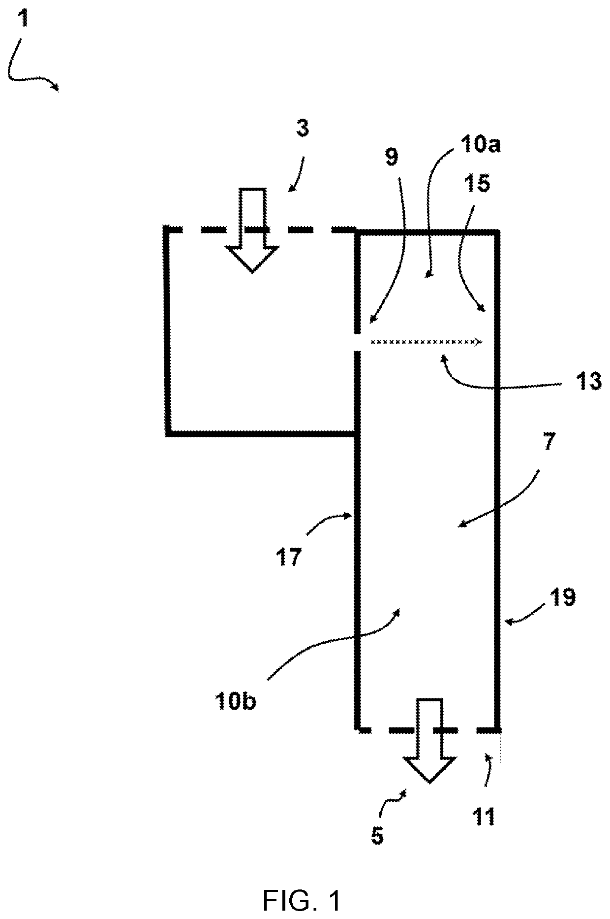
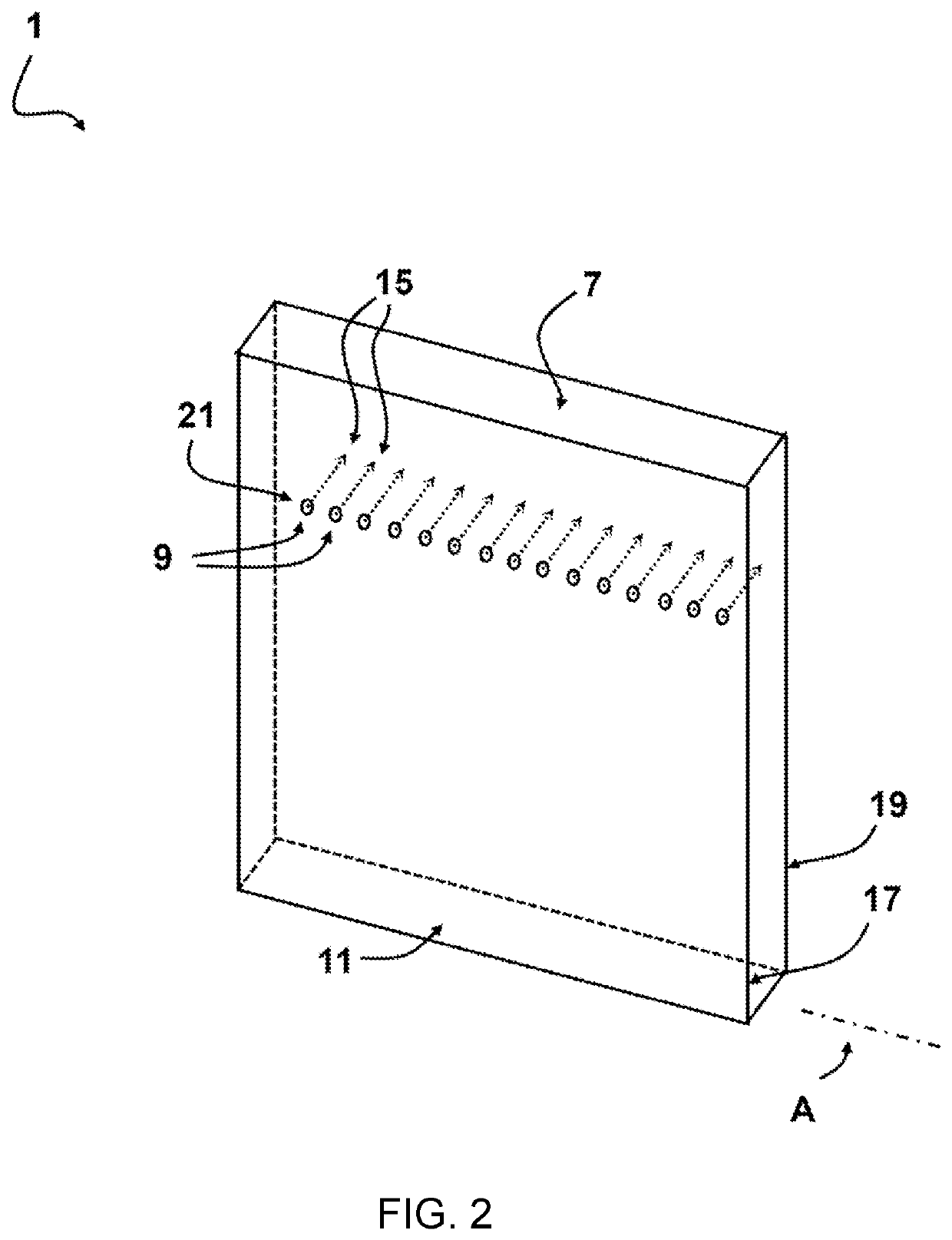
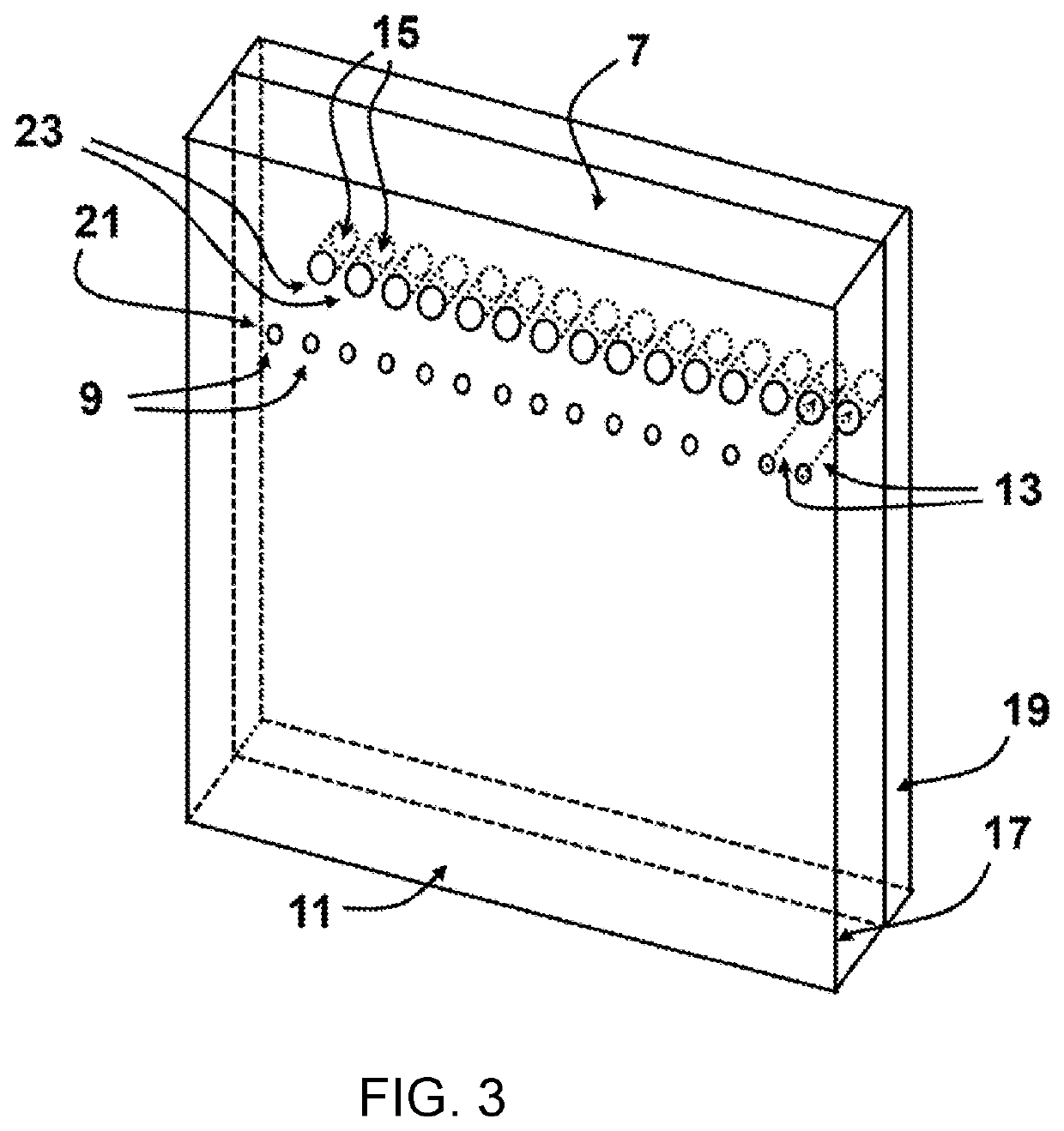
[0118]FIG. 1 shows a cross sectional view of a schematic diagram of an embodiment of a fluid handling structure 1 for a gas phase deposition apparatus. The structure 1 defines a flow path with an inlet 3 and an outlet 5 for transmitting pressurized fluid from said inlet 3 to the outlet 5. The structure 1 includes an elongated slit 7 and a series of nozzles 9 (only one visible in this cross section) through which pressurized fluid is allowed to enter the elongated slit 7. The inlet 3 of the fluid handling structure 1 is positioned upstream the series of nozzles 9 in the flow path. defined by said fluid handling structure 1. The outlet 5 is formed downstream in the flow path, at a gap opening 11 of the elongated slit 7, through which pressurized fluid is allowed to discharge from the elongated slit 7. The series of nozzles 9 are configured to provide a larger flow resistance than the elongated slit 7. The series of nozzles 9 are adapted to form a series of jet flows 13 directed toward...


PUM

PropertyMeasurementUnit
Lengthaaaaaaaaaa
Lengthaaaaaaaaaa
Diameteraaaaaaaaaa

Abstract

A fluid handling structure for a gas phase deposition apparatus, the structure defining a flow path with an inlet and an outlet for transmitting pressurized fluid from said inlet to the outlet, wherein the structure includes an elongated slit and a series of nozzles through which pressurized fluid is allowed to enter the elongated slit, the inlet being upstream the series of nozzles, and wherein the outlet is formed downstream at a gap opening of the elongated slit allowing pressurized fluid to discharge from the elongated slit towards a substrate, wherein the series of nozzles are configured to provide a larger flow resistance than the elongated slit, and wherein the series of nozzles are adapted to form a series of jet flows directed towards one or more impingement surfaces of the structure when pressurized fluid is transmitted through the flow path.

Description

FIELD OF THE INVENTION[0001]The invention relates to a fluid handling for a gas phase deposition apparatus. The invention also relates to a fluid delivery head for use in a gas phase deposition system, and a gas phase deposition system including a fluid delivery head with the fluid handling structure. The invention further relates to a method for improving homogeneity of fluid flows produced for gas phase deposition on substrates. Further, the invention relates to a method for manufacturing a fluid handling structure for a gas phase deposition apparatus.BACKGROUND TO THE INVENTION[0002]A gas phase deposition technique is thin-film deposition used for providing a thin layer of material on a substrate or onto previously deposited layers. In most gas phase deposition techniques, a layer thickness can be controlled within a few tens of nanometers to several micrometers.[0003]Atmospheric pressure large area gas phase deposition equipment, such as for instance spatial atomic layer deposit...

Claims


Application Information

Patent Timeline
IPC IPC(8): C23C16/455
CPCC23C16/45578C23C16/45557B05B7/0012B05B1/267C23C16/45563C23C16/45502C23C16/45551
Inventor OLIESLAGERS, RUUDSMELTINK, JEROEN ANTHONIUS
Owner NEDERLANDSE ORG VOOR TOEGEPAST-NATUURWETENSCHAPPELIJK ONDERZOEK (TNO)
Why Eureka
Try Eureka