
Vapor distributor for a mass transfer column and method involving same

a technology of mass transfer column and distributor, which is applied in the direction of separation process, petrochemical, chemical and other process applications, etc., can solve the problems of significant portions of the vapor stream to be deflected downward, cannot be varied to improve the vapor redistribution, and cannot be suitable for refining separation, etc., to achieve the effect of reducing the radial velocity

Pending Publication Date: 2022-05-12
KOCH GLITSCH INC
View PDF0 Cites 0 Cited by
  • Summary
  • Abstract
  • Description
  • Claims
  • Application Information

AI Technical Summary

Benefits of technology

The patent describes a way to distribute a vapor stream in a mass transfer column. It includes using braces that are positioned in a way that they extend across the array of deflectors and are spaced apart from each other. The method involves introducing the vapor stream into the shell of the column in a radial direction through a radial inlet and then redirecting the vapor stream upwardly by causing it to be redirected from the radial direction by the deflecting surfaces of the deflectors in the array of deflectors. This results in a more even distribution of the vapor stream within the column.

Problems solved by technology

While these types of vapor distributors can function satisfactorily in many applications, they may not be suitable for refining separation, petrochemical, chemical and other process applications in which severe conditions such as fouling, coking, erosion, and corrosion are a problem.
While the circular cross section of the deflectors is advantageous in that it inhibits the deposition of material from the vapor stream onto the deflectors, it is also disadvantageous because it tends to cause significant portions of the vapor stream to be deflected in the downward direction rather than in the desired upward direction.
A further disadvantage of the circular cross section of the deflectors is the convex deflecting surface that is impacted by the vapor stream remains the same and cannot be varied to improve the vapor redistribution by changing the rotational positioning of some or all of the individual deflectors during construction of the vapor distributor.

Method used


Image

  • Vapor distributor for a mass transfer column and method involving same
  • Vapor distributor for a mass transfer column and method involving same
  • Vapor distributor for a mass transfer column and method involving same

Examples


Embodiment Construction

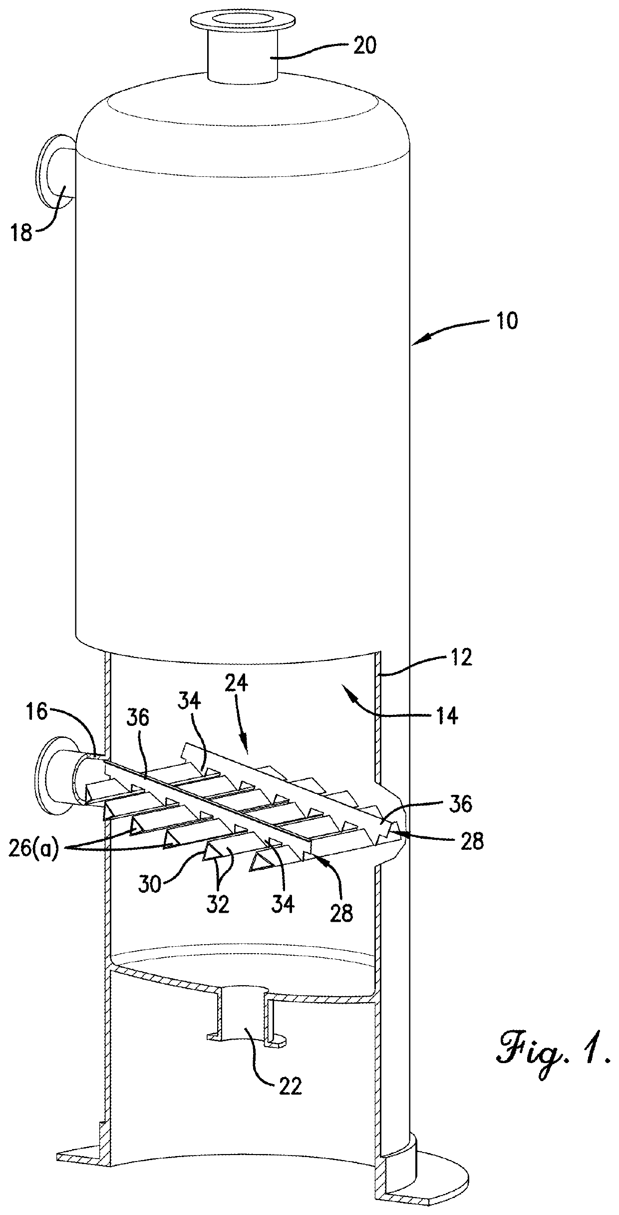
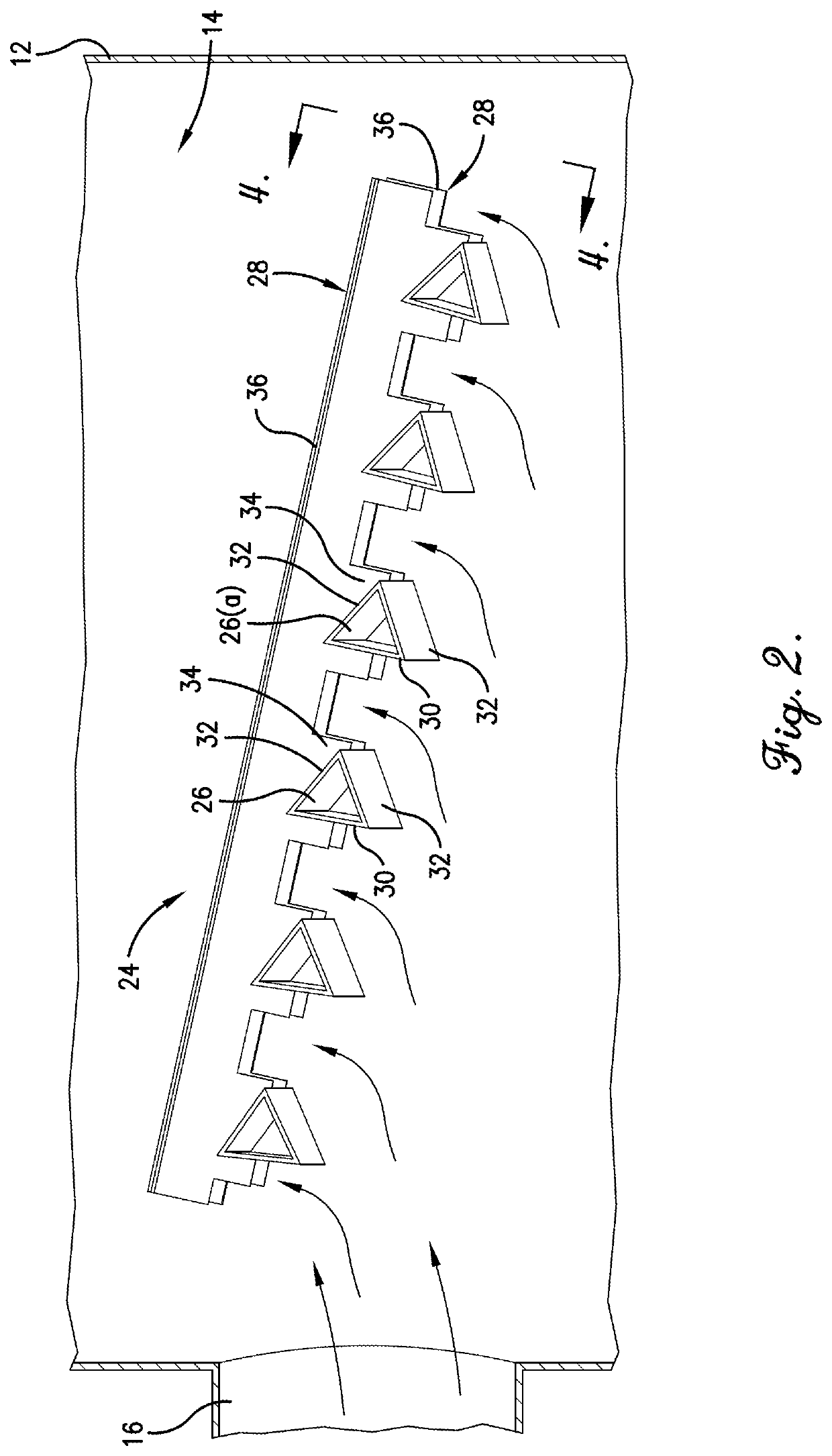
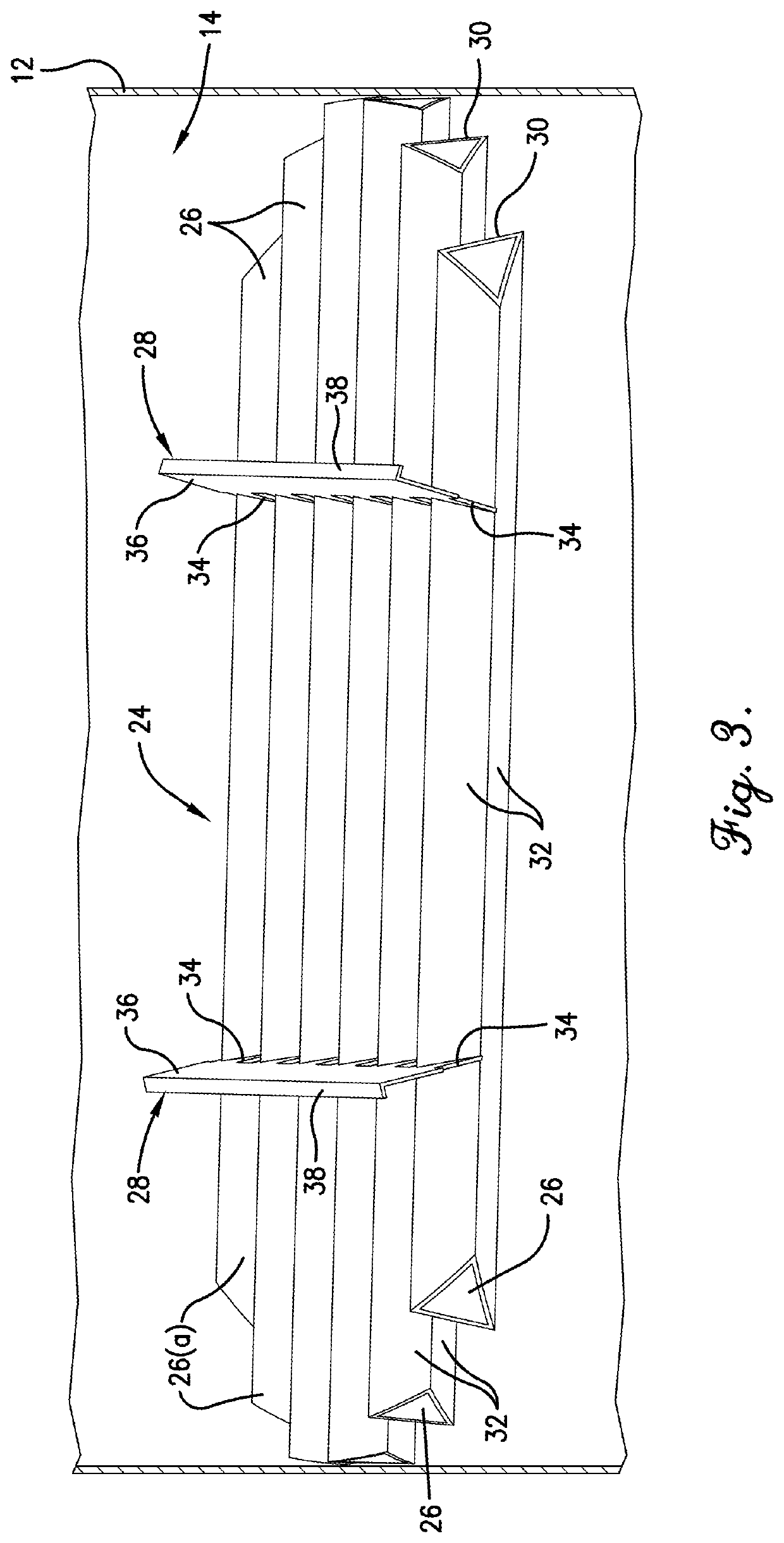
[0018]Turning now to the drawings in greater detail, and initially to FIG. 1, a mass transfer column is designated generally by the numeral 10 and includes an upright cylindrical shell 12 that defines an open internal region 14. The shell 12 is of any suitable diameter and height and is constructed from suitably rigid materials that are preferably inert to, or otherwise compatible with the fluids and conditions present within the mass transfer column 10. Although the shell 12 of the mass transfer column 10 is shown in a cylindrical configuration, other shapes, including polygonal, may be used.

[0019]The mass transfer column 10 is of a type used to process fluid streams, including in refining separation, petrochemical, chemical and other process applications in which severe conditions such as fouling, coking, erosion, and corrosion are a problem. The fluid streams comprise one or more ascending vapor streams and one or more descending liquid streams. One of the vapor streams is direct...


PUM


Abstract

A vapor distributor for use in an internal region of a mass transfer column to receive and redistribute a vapor stream when it is introduced radially into the internal region through a radial inlet in a shell of the mass transfer column. The vapor distributor includes a plurality of multiple-sided elongated deflectors arranged in a descending array and a pair of braces that extend longitudinally across the array of elongated deflectors and hold them in spaced apart and side-by-side relationship to each other. Each of the elongated deflectors has a deflecting surface that faces toward the radial inlet to redirect and redistribute the radially-introduced vapor stream. The braces each include a strut that may also redirect and redistribute the vapor stream.

Description

RELATED APPLICATIONS[0001]This application is a National Phase of International Application No. PCT / IB2020 / 052468 filed on Mar. 18, 2020, which claims priority to U.S. Provisional Patent Application No. 62 / 822,397, filed Mar. 22, 2019, and U.S. Provisional Patent Application No. 62 / 903,942, filed Sep. 23, 2019, the contents of which are incorporated herein by reference in their entireties.TECHNICAL FIELD[0002]The present disclosure relates generally to mass transfer columns and, more particularly, to vapor distributors for receiving and redistributing a vapor stream introduced into the mass transfer column from a radial inlet and methods of redistributing the vapor stream using the vapor distributors.BACKGROUND ART[0003]Mass transfer columns are configured to contact at least two fluid streams in order to provide product streams of specific composition and / or temperature. The term “mass transfer column,” as used herein is intended to encompass columns in which mass and / or heat trans...

Claims


Application Information

Patent Timeline
Patent Type & Authority Applications(United States)
IPC IPC(8): B01D3/32B01D3/26
CPCB01D3/32B01D3/26B01D1/0064B01D3/008
Inventor NIEUWOUDT, IZAKTALBOT, MALCOLM
Owner KOCH GLITSCH INC
Learn More