Eureka AIR delivers breakthrough ideas for toughest innovation challenges, trusted by R&D personnel around the world.

Method and circuit for calibrating wireless transceiver

a wireless transceiver and wireless technology, applied in the direction of receiver monitoring, electrical equipment, transmitter monitoring, etc., can solve the problems of poor linearity, poor and process errors in mass production, so as to improve the flatness of the wireless transceiver and improve the linearity

Active Publication Date: 2022-04-07
REALTEK SEMICON CORP
View PDF5 Cites 0 Cited by
  • Summary
  • Abstract
  • Description
  • Claims
  • Application Information

AI Technical Summary

Benefits of technology

The aim of this patent is to provide a way to calibrate wireless transceivers that improves their flatness. The traditional methods caused issues of circuit saturation and poor linearity, but this new technology provided by the present invention helps resolve these issues.

Problems solved by technology

However, there are often process errors in mass production.
If the process error exceeds the tolerance range of the parameters set during development, the flatness of the wireless transceiver will not be as desired.
Both poor linearity and circuit saturation degrade the performance of the wireless transceiver.

Method used

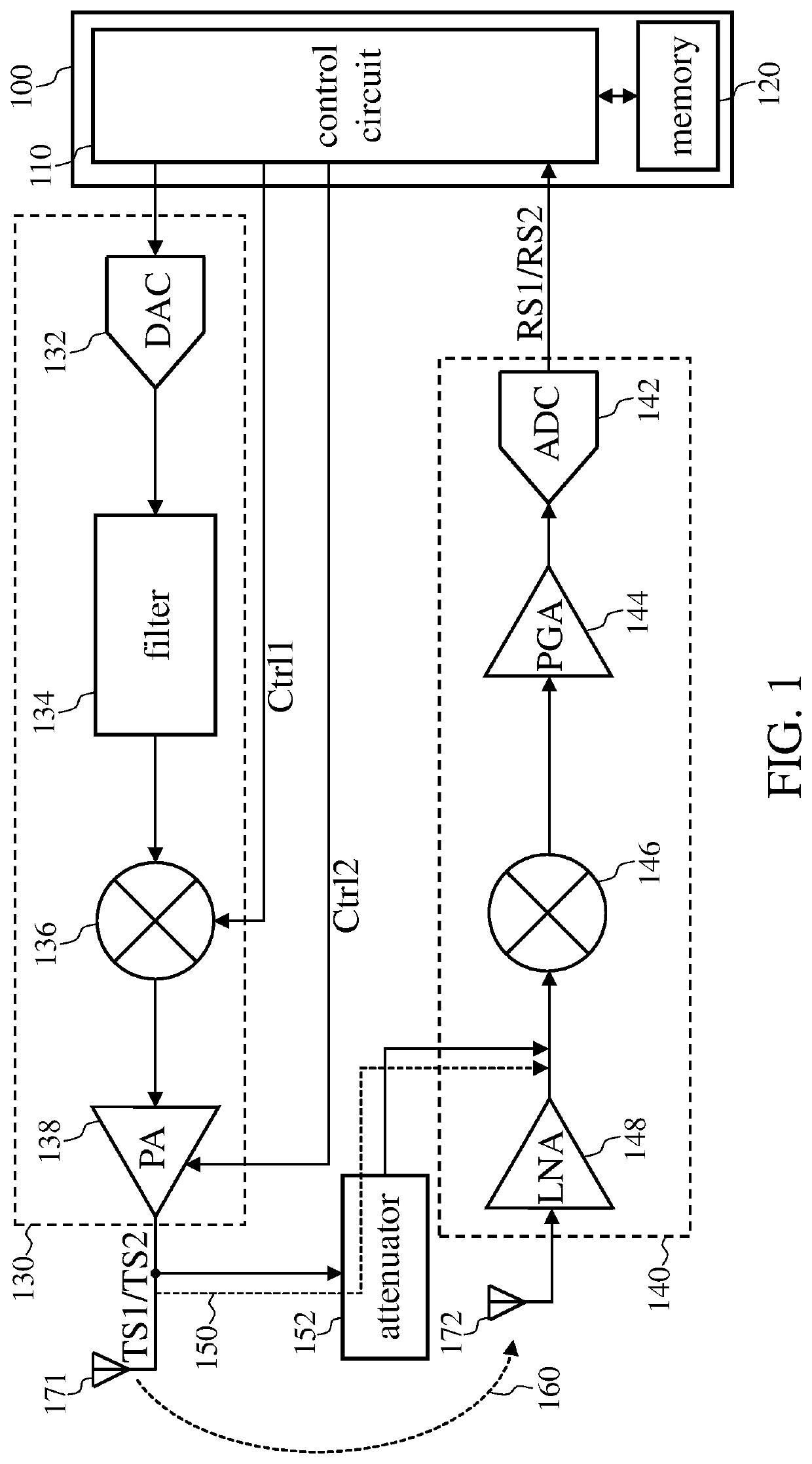
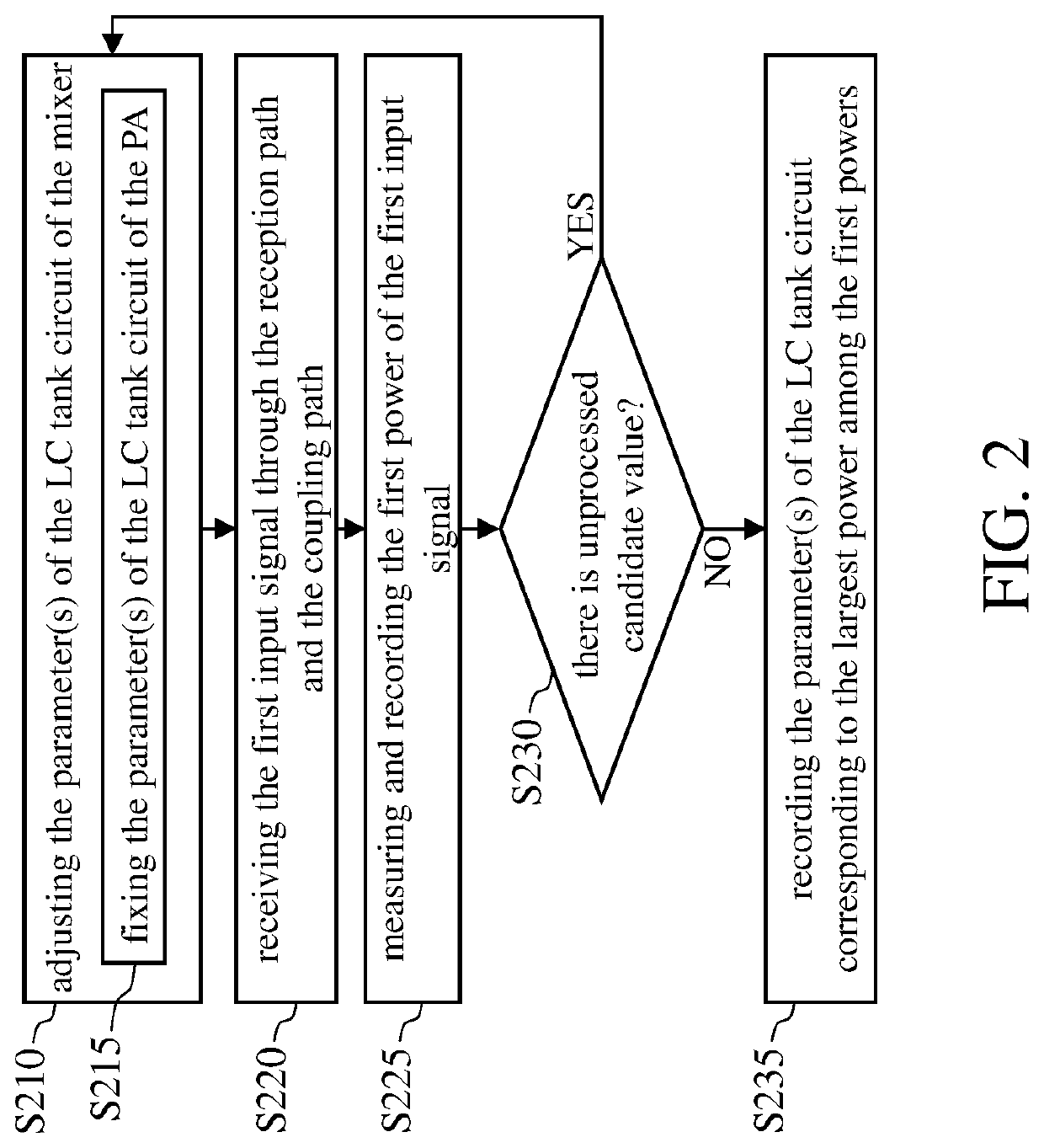
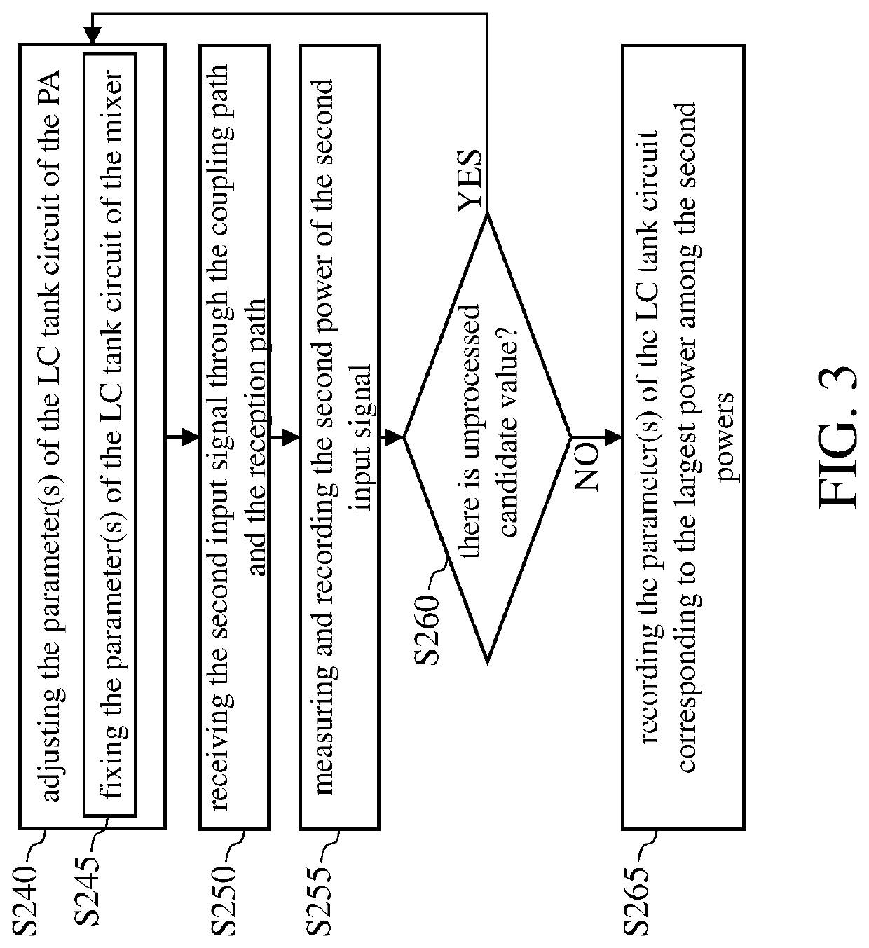

Image

  • Method and circuit for calibrating wireless transceiver
  • Method and circuit for calibrating wireless transceiver
  • Method and circuit for calibrating wireless transceiver

Examples


Embodiment Construction

[0015]The following description is written by referring to terms of this technical field. If any term is defined in this specification, such term should be interpreted accordingly. In addition, the connection between objects or events in the below-described embodiments can be direct or indirect provided that these embodiments are practicable under such connection. Said “indirect” means that an intermediate object or a physical space exists between the objects, or an intermediate event or a time interval exists between the events.

[0016]The disclosure herein includes a method and a circuit for calibrating wireless transceivers. On account of that some or all elements of the wireless transceiver could be known, the detail of such elements is omitted provided that such detail has little to do with the features of this disclosure, and that this omission nowhere dissatisfies the specification and enablement requirements. Some or all of the processes of the method of calibrating wireless t...


PUM


Abstract

The present invention discloses a calibration method and calibration circuit for a wireless transceiver. The wireless transceiver includes a transmission path and a reception path, and there is a mixer on the transmission path. The calibration method includes the following steps: (A) adjusting a first parameter of a first LC tank circuit of the mixer; (B) receiving a first input signal via a coupling path and the reception path; (C) measuring a first power of the first input signal; (D) repeating steps (A) to (C) to obtain multiple first powers; and (E) determining a first target parameter corresponding to a largest power of the first powers.

Description

BACKGROUND OF THE INVENTION1. Field of the Invention[0001]The present invention generally relates to wireless transceivers, and, more particularly, to a method and a circuit for calibrating the wireless transceivers.2. Description of Related Art[0002]A wireless transceiver can operate in multiple bands, and there are multiple channels in one band. Wireless transceivers are usually designed to output the same power over various channels of the same band; that is, wireless transceivers are usually desired to be of high flatness.[0003]In the design stage, the LC tank circuit of the radio frequency (RF) circuit of the wireless transceiver needs to be optimally adjusted to set the parameters (i.e., inductance and capacitance), so that the frequency response of the RF circuit has the best flatness. However, there are often process errors in mass production. If the process error exceeds the tolerance range of the parameters set during development, the flatness of the wireless transceiver w...

Claims


Application Information

Patent Timeline
Patent Type & Authority Applications(United States)
IPC IPC(8): H04B17/11H04B1/40H04B17/21
CPCH04B17/11H04B17/21H04B1/40H04B1/525H04B17/13
Inventor HUANG, CHIEN-JUNGLU, YI-HUA
Owner REALTEK SEMICON CORP
Why Eureka
Eureka Blog
Learn More