
System and method for controlling vehicle

a technology of system and method, applied in the direction of vehicle components, vehicle suspensions, understructures, etc., can solve the problems of difficult maintenance of air pressure adjustment devices in the related art, decrease in vehicle height, etc., and achieve the effect of reducing the length of the connection devices

Active Publication Date: 2022-04-07
HYUNDAI MOBIS CO LTD
View PDF11 Cites 3 Cited by
  • Summary
  • Abstract
  • Description
  • Claims
  • Application Information

AI Technical Summary

Benefits of technology

The patent text describes a system that can adjust the height of a vehicle to different road surfaces. It can detect the height displacement of the road and increase or decrease the vehicle height by adjusting the front and rear wheels' velocities and the length of the connection devices. The controller can also increase the velocity difference between the front and rear wheels or adjust the shock absorbers to achieve the desired vehicle height. This system can improve the vehicle's stability and comfort on different road surfaces.

Problems solved by technology

There is a problem in that the air pressure adjustment device in the related art is difficult to maintain.
Further, there is a problem in that when the air pressure adjustment device is broken down, the air pressure decreases, which causes a decrease in vehicle height.

Method used


Image

  • System and method for controlling vehicle
  • System and method for controlling vehicle
  • System and method for controlling vehicle

Examples


first embodiment

[0122]FIG. 9 is a view illustrating the vehicle control system according to the embodiment of the present invention for implementing the deviation between the left and right sides of the vehicle.

[0123]The independent driving module 100 includes a steering device 140 configured to steer a direction of the wheel 200 by rotating the connection device 110. When the deviation between the left and right sides is inputted to the input unit 10 to incline the vehicle to the left or right side, the control unit 20 may control the steering device 140 to rotate the wheel 200, which is disposed in a direction opposite to the direction in which the vehicle is inclined, from the center of the vehicle to the outside of the vehicle, and the control unit 20 may control the driving device to rotate the wheel 200 to the outside of the vehicle.

[0124]The independent driving module 100 may have the steering device 140 that adjusts the direction of the wheel 200 by rotating the connection device 110.

[0125]...

second embodiment

[0126]FIG. 10 is a view illustrating the vehicle control system according to the embodiment of the present invention for implementing the deviation between the left and right sides of the vehicle.

[0127]When the deviation between the left and right sides is inputted to the input unit 10 to incline the vehicle to the left or right side, the control unit 20 may control the driving devices to rotate the front and rear wheels 200, which are disposed in the direction in which the vehicle is inclined, from the center of the vehicle to the outside of the vehicle.

[0128]Further referring to FIG. 10, when the deviation between the left and right sides of the vehicle is inputted to the input unit 10, the control unit 20 controls the driving device in the direction opposite to the direction in which the vehicle is inclined to rotate the front and rear wheels toward the center of the vehicle in the direction opposite to the direction in which the vehicle is inclined. As a result, the connection l...


PUM


Abstract

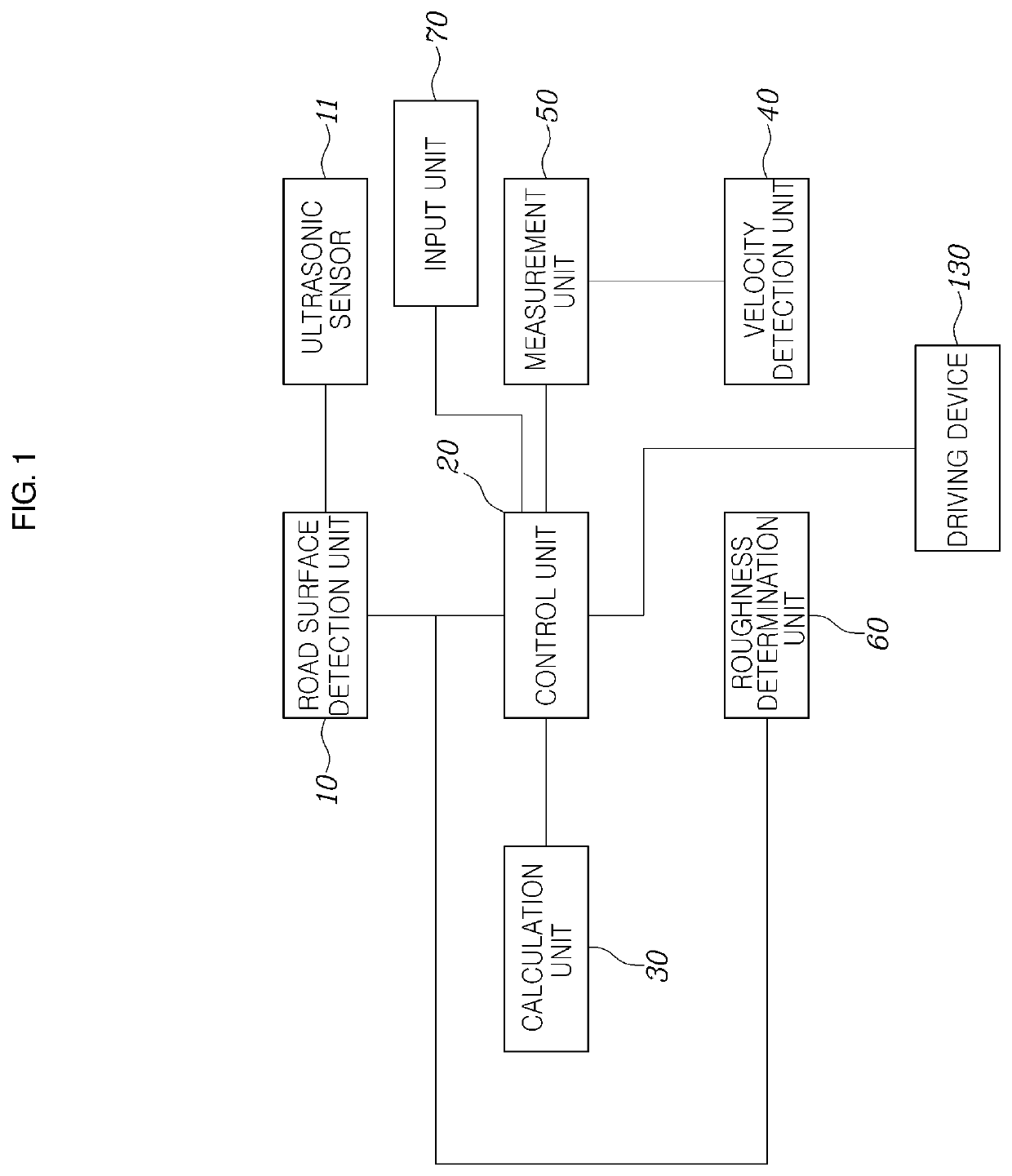
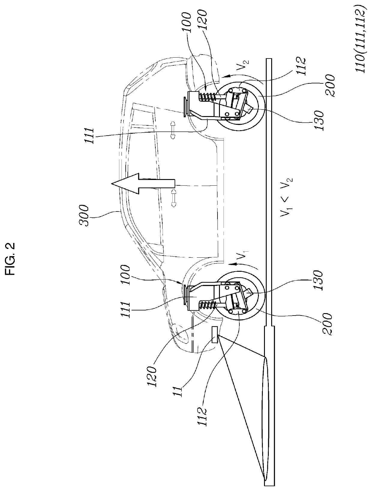
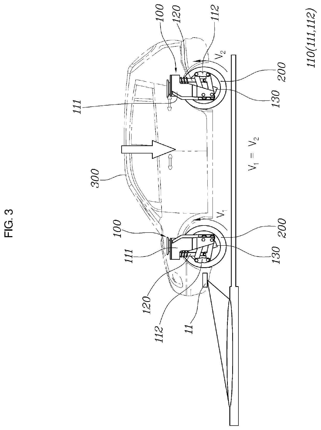
A system and method for controlling a vehicle, where the system includes independent driving modules each including a connection device having a rotation center spaced apart from a driving shaft in a forward / rearward direction and configured to connect the wheel and a vehicle body to move the wheel in the forward / rearward or an upward / downward direction, a shock absorber extending in a longitudinal direction and configured to contract or stretch, to connect the vehicle body and the connection device, and to restrict an upward / downward movement of the connection device, and a driving device configured to rotate the wheel, a road surface detector configured to detect a height displacement or a state of a road, and a controller configured to control velocities of the front and rear wheels of the independent driving modules, and to change a height of the vehicle based on the height displacement or the state of the road.

Description

CROSS REFERENCE TO RELATED APPLICATION[0001]The application claims the benefit under 35 USC 119(a) of Korean Patent Application No. 10-2020-0177659, filed on Dec. 17, 2020 and to Korean Application No. 10-2020-0129634, filed on Oct. 7, 2020, in the Korean Intellectual Property Office, the entire disclosure of which are incorporated herein by reference for all purposes.BACKGROUND OF THE INVENTIONField of the Invention[0002]The following description relates to a system and method for controlling a vehicle, and more particularly, to a technology for adjusting a vehicle height of a vehicle by controlling an independent driving module mounted in the vehicle.Description of the Related Art[0003]A separate air pressure adjustment device is mounted in a vehicle in the related art to adjust a vehicle height of the vehicle when a passenger gets in or out of the vehicle or freight is loaded or to adjust an air pressure of a suspension mounted in the vehicle to implement a deviation between left...

Claims


Application Information

Patent Timeline
Patent Type & Authority Applications(United States)
IPC IPC(8): B60G17/0165B60G17/018
CPCB60G17/0165B62D21/14B60G2500/30B60G17/018B60G3/185B60G2200/13B60G2300/37B60G2200/44B60G2200/422B60G2300/50B60G2400/82B60G2400/252B60G2500/40B60G2400/208B60G2800/213B60G2401/176B60G2600/182B60G2400/40
Inventor HAN, SANG OHCHOI, WON HYOKLEE, TAE HEONMIN, KYONGWON
Owner HYUNDAI MOBIS CO LTD
Learn More