Optical connector and power sourcing equipment of power over fiber system, and power over fiber system

a technology of optical connectors and power sourcing equipment, applied in the field of optical power supplies, to achieve the effect of high-energy ligh

Active Publication Date: 2022-03-24
KYOCERA CORP
View PDF0 Cites 1 Cited by
  • Summary
  • Abstract
  • Description
  • Claims
  • Application Information

AI Technical Summary

Benefits of technology

The present patent text describes an optical connector for a power over fiber system that has a shutter that opens when connecting and closes to block the feed light from exiting. The light receiving surface of the shutter is a mirror plane. The optical connector is located at the output end of the power over fiber system. The technical effect of this patent text is to provide a reliable and efficient connection between two optical fibers for the transmission of power.

Problems solved by technology

If a connector is and keeps being disengaged by an unforeseen incident during installation or operation of a power over fiber system, it may lead to an accident caused by energy of feed light.

Method used


Image

  • Optical connector and power sourcing equipment of power over fiber system, and power over fiber system
  • Optical connector and power sourcing equipment of power over fiber system, and power over fiber system
  • Optical connector and power sourcing equipment of power over fiber system, and power over fiber system

Examples


first embodiment

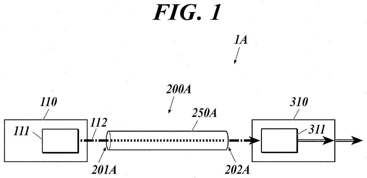
[0016]As shown in FIG. 1, a power over fiber (PoF) system 1A of this embodiment includes a power sourcing equipment (PSE) 110, an optical fiber cable 200A and a powered device (PD) 310.

[0017]In the present disclosure, a power sourcing equipment converts electric power into optical energy and supplies (sources) the optical energy, and a powered device receives (draws) the supplied optical energy and converts the optical energy into electric power.

[0018]The power sourcing equipment 110 includes a semiconductor laser 111 for power supply.

[0019]The optical fiber cable 200A includes an optical fiber 250A that forms a transmission path of feed light.

[0020]The powered device 310 includes a photoelectric conversion element 311.

[0021]The power sourcing equipment 110 is connected to a power source, and electrically drives the semiconductor laser 111 and so forth.

[0022]The semiconductor laser 111 oscillates with the electric power from the power source, thereby outputting feed light 112.

[0023]...

second embodiment

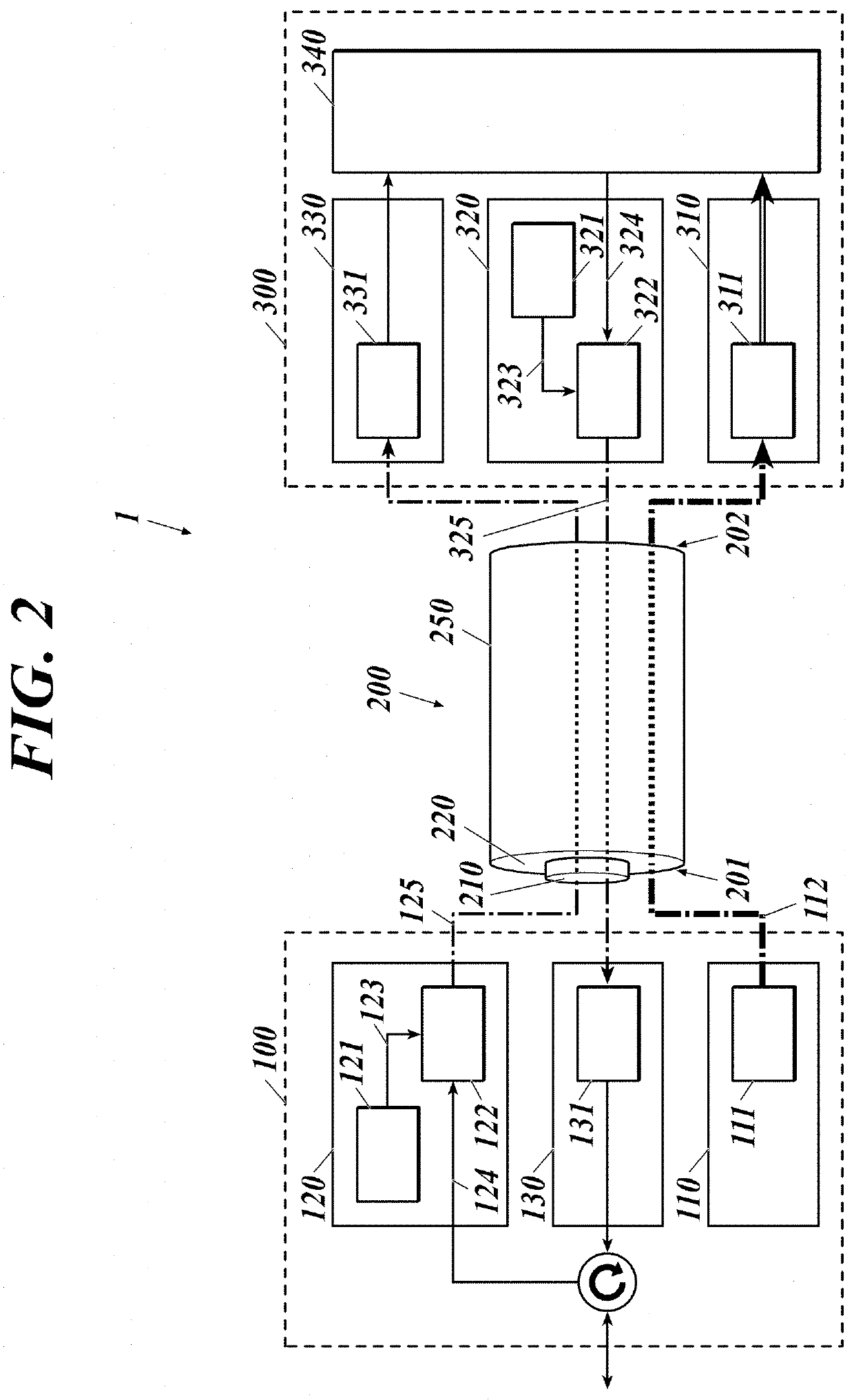
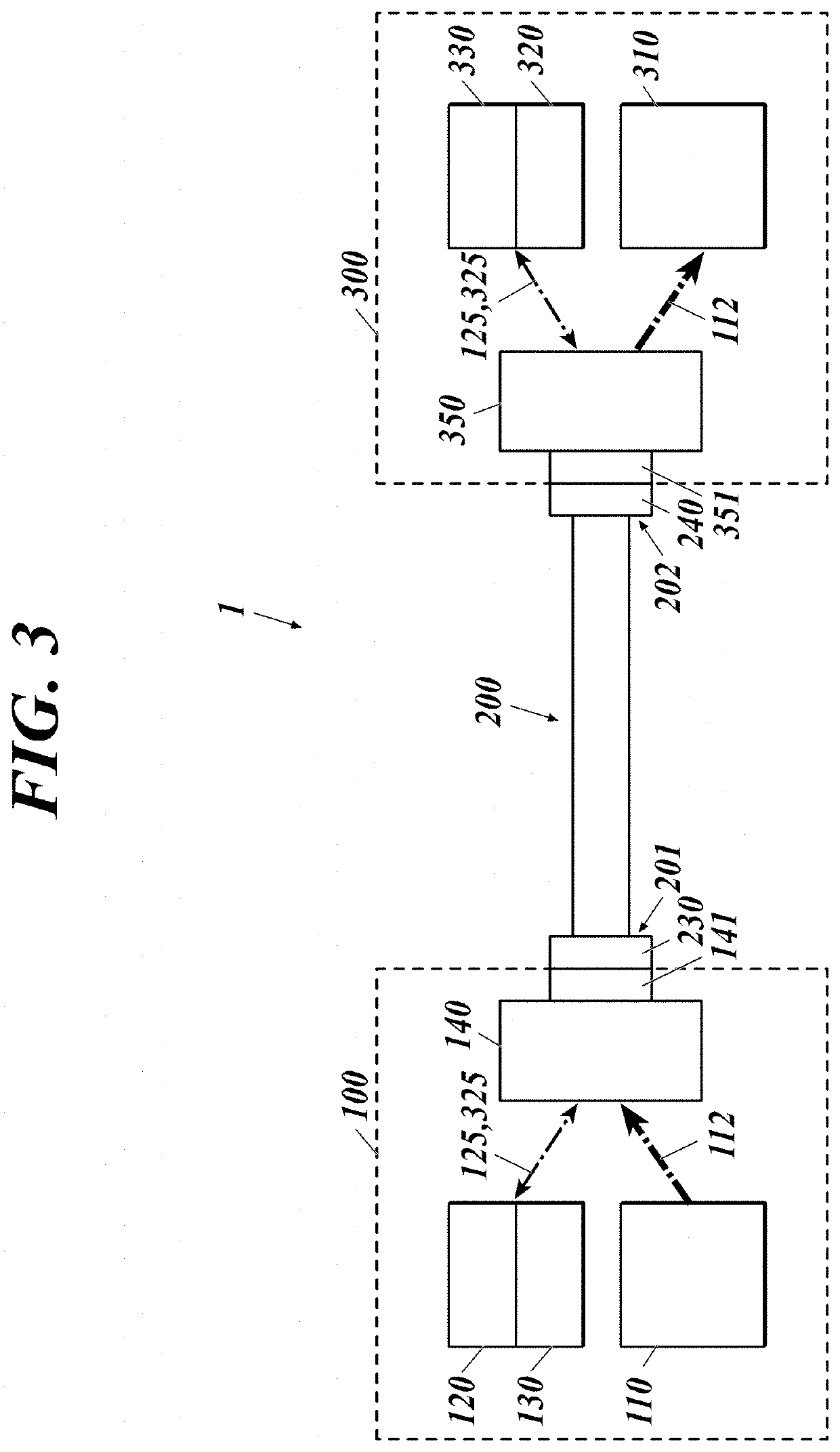
[0033]As shown in FIG. 2, a power over fiber (PoF) system 1 of this embodiment includes a power supply system through an optical fiber and an optical communication system therethrough, and includes: a first data communication device 100 including a power sourcing equipment (PSE) 110; an optical fiber cable 200; and a second data communication device 300 including a powered device (PD) 310.

[0034]The power sourcing equipment 110 includes a semiconductor laser 111 for power supply. The first data communication device 100 includes, in addition to the power sourcing equipment 110, a transmitter 120 and a receiver 130 for data communication. The first data communication device 100 corresponds to a data terminal equipment (DTE), a repeater or the like. The transmitter 120 includes a semiconductor laser 121 for signals and a modulator 122. The receiver 130 includes a photodiode 131 for signals.

[0035]The optical fiber cable 200 includes an optical fiber 250 including: a core 210 that forms a...


PUM


Abstract

An optical connector of a power over fiber system includes a shutter. The shutter opens in conjunction with a connection operation to enable the connection and closes in conjunction with a disconnection operation to block feed light from exiting. A light receiving surface of the shutter is made of a wavelength conversion material. The light receiving surface receives the feed light when the shutter is closed. The optical connector is disposed at a feed-light output end in the power over fiber system.

Description

TECHNICAL FIELD[0001]The present disclosure relates to optical power supply.BACKGROUND ART[0002]Recently, there has been studied an optical power supply system that converts electric power into light (called feed light), transmits the feed light, converts the feed light into electric energy, and uses the electric energy as electric power.[0003]There is disclosed in Patent Literature 1 an optical communication device that includes: an optical transmitter that transmits signal light modulated with an electric signal and feed light for supplying electric power; an optical fiber including a core that transmits the signal light, a first cladding that is formed around the core, has a refractive index lower than that of the core, and transmits the feed light, and a second cladding that is formed around the first cladding, and has a refractive index lower than that of the first cladding; and an optical receiver that operates with electric power obtained by converting the feed light transmit...

Claims


Application Information

Patent Timeline
IPC IPC(8): H04B10/80G02B6/42H01S5/042
CPCH04B10/807H01S5/042G02B6/4206H02J4/00H02J50/30G02B6/4296G02B2006/4297G02B6/4292G02B6/3895H04B2210/08
Inventor SUYAMA, TAKEHIKO
Owner KYOCERA CORP
Why Eureka
Try Eureka