Apparatus and system for securing hardware to a structure utilizing torsional joints

a technology of torsional joints and hardware, which is applied in the direction of sheet joining, electrical appliances, fastening means, etc., can solve the problems of affecting the use effect, thick material causing a tearing moment strain on the connection ends, etc., and achieves the effect of facilitating rotation ninety degrees, and reducing the number of brackets

Active Publication Date: 2022-03-17
STECHMANN ERIC
View PDF7 Cites 2 Cited by
  • Summary
  • Abstract
  • Description
  • Claims
  • Application Information

AI Technical Summary

Benefits of technology

[0024]The disclosed apparatus and system provide that material spacing between the distal fastening pad and bracketing body allows manual control of the bracket in the manner of installation, adjustment, removal, and manual rotation of the pad upon the axis of rotation. Distal pads, and the associated attached devices mounted to the distal pads, can readily be rotated ninety degrees, or more, to accommodate complex topographies. Additionally, the distal pads, torsional joints and main body may be comprised of a monolithic material or fastened together from separate components in any arrangement that bonds these functional members together.
[0025]It is an object of the apparatus as disclosed herein to be able to accommodate a wide range of building surface geometries thereby reducing the number of brackets that are required within the inventory. Because of the considerable flexibility and adaptability of the apparatus disclosed herein it offers the user a far greater range of applications per any main body configuration.

Problems solved by technology

A torsional joint that is too narrow does not effectively use the material thickness and a torsional joint that is too thick creates a tearing moment strain on the connection ends.

Method used


Image

  • Apparatus and system for securing hardware to a structure utilizing torsional joints
  • Apparatus and system for securing hardware to a structure utilizing torsional joints
  • Apparatus and system for securing hardware to a structure utilizing torsional joints

Examples


Embodiment Construction

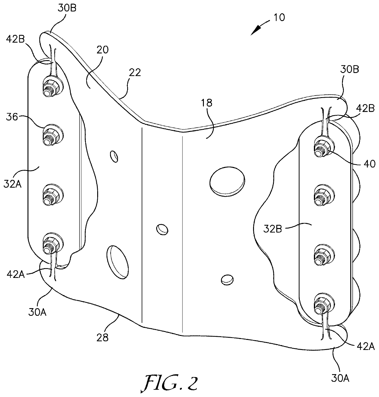
[0042]The disclosed technology is directed to an apparatus for securing hardware to a structure through various attachment mechanisms. By using torsional deflection of joints fabricated within the apparatus itself, the apparatus can align the selected attachment mechanism to the topography of the surface of the structure. The surface of the structure can be flat, stepped, concave, convex, or form any number of angles.

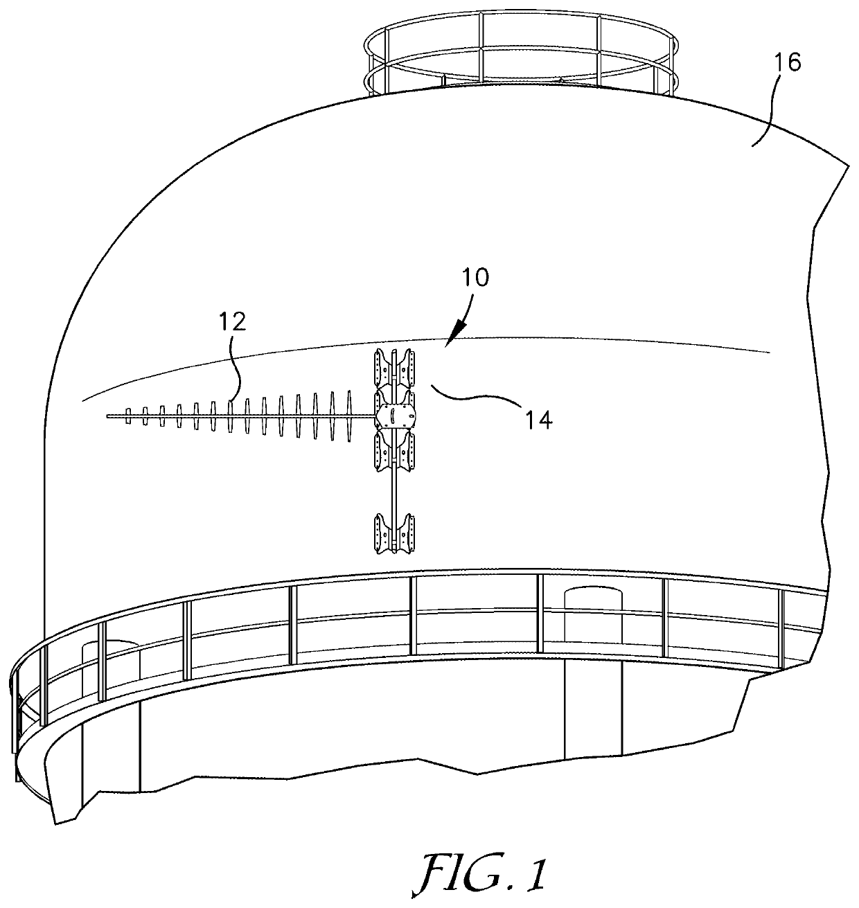
[0043]FIG. 1 illustrates an embodiment of the apparatus 10 for securing hardware 12 to a surface 14 of a structure 16 as disclosed herein. As detailed above, the apparatus 10, also commonly referred to in some instances as a bracket, is used to secure the hardware 12 such as antennas, conduit, and cabling, among other items, to the surface 14 of the structure 16. The structure in this instance may be a water tower, an exterior substrate of a building, a cell tower, or any other structure to which a bracketing apparatus need be applied.

[0044]In a first embodiment as illu...


PUM


Abstract

Disclosed herein is an apparatus for mounting hardware to a surface of a structure. The apparatus includes a main body with an upper surface, a lower surface, and an outer edge. The apparatus also includes a distal pad with an upper and a lower planar surface, the distal pad being attached to the main body by at least two torsional joints. The apparatus also includes an attachment device with a contact surface, the attachment device is mounted to at least one of the planar surfaces. The contact surface is for engagement with the surface of the structure. The at least two torsional joints and distal pad may be manually rotated to achieve maximal surficial contact between the surface of the structure and the contact surface of the attachment device.

Description

RELATED APPLICATIONS[0001]This application is a continuation-in-part application of U.S. application Ser. No. 17 / 018,522 filed on Sep. 11, 2020 which is a continuation in part to U.S. application Ser. No. 15 / 437,000 filed on Feb. 20, 2017, now U.S. Pat. No. 10,808,883 which issued on Oct. 20, 2020, which is a continuation-in-part to U.S. application Ser. No. 15 / 009,398 filed on Jan. 28, 2016, now U.S. Pat. No. 9,577,417 which issued on Feb. 21, 2017, which is a continuation-in-part to U.S. application Ser. No. 14 / 252,629 filed on Apr. 4, 2014, now U.S. Pat. No. 9,252,581 which issued on Feb. 2, 2016 which claims priority from U.S. Provisional Application No. 61 / 811,424 filed Apr. 12, 2013. The contents of these applications are incorporated herein by reference in their entireties.FIELD OF THE DISCLOSURE[0002]This disclosure relates to brackets and mounting systems. More specifically, this disclosure concerns brackets and mounting systems for securing hardware to structures in a wide...

Claims


Application Information

Patent Timeline
Patent Type & Authority Applications(United States)
IPC IPC(8): F16B5/00
CPCF16B5/0004F16L3/221F16L3/24H02G3/32H02G3/34F16B17/008F16B5/0614F16B5/065F16B5/0216F16B5/02F16B5/0096F16L13/00F16L3/00F16B1/00
Inventor STECHMANN, ERIC
Owner STECHMANN ERIC
Why Eureka
Try Eureka