
Sacroiliac fusion system

a fusion system and sacroiliac joint technology, applied in the field of sacroiliac joint fusion system, can solve the problems of preventing the patient from fully absorbing the sacroiliac joint, causing the patient to experience more pain, and damage to the tissue, nerves and/or blood vessels surrounding the sacroiliac joint,

Pending Publication Date: 2022-03-10
SURGALIGN SPINE TECH INC
View PDF0 Cites 4 Cited by
  • Summary
  • Abstract
  • Description
  • Claims
  • Application Information

AI Technical Summary

Benefits of technology

The invention is about an apparatus and method for performing an orthopedic procedure in the sacroiliac region. The apparatus includes an insertion apparatus, probe assembly, and cutting assembly. The cutting assembly is a sharper tool that is used to create a fusion region between the ilium and the sacrum. The procedure involves inserting the undercutting system into the sacroiliac region, manipulating the probe assembly and cutting assembly to create a fusion region, and then removing the undercutting system. The method also includes using a fastening device to retain the ilium and sacrum in a stationary position with respect to each other. The technical effects of this invention include improved precision and efficiency in creating a fusion region between the ilium and sacrum and reduced trauma to the patient during the procedure.

Problems solved by technology

If initial efforts to reduce the pain in the sacroiliac joint through physical therapy and / or steroid injections are not effective, surgery may be needed to fuse together the sacroiliac joint.
Because of the challenges in accessing the surfaces of the sacrum and the ilium that will fuse together, this type of surgery may result in damage to tissue, nerves and / or blood vessels that surround the sacroiliac joint.
Such damage may prevent the patient from fully realizing the benefits of the sacroiliac joint fusion and in some instances cause the patient to experience more pain after the sacroiliac joint fusion than before the sacroiliac joint fusion.

Method used


Image

  • Sacroiliac fusion system
  • Sacroiliac fusion system
  • Sacroiliac fusion system

Examples


Embodiment Construction

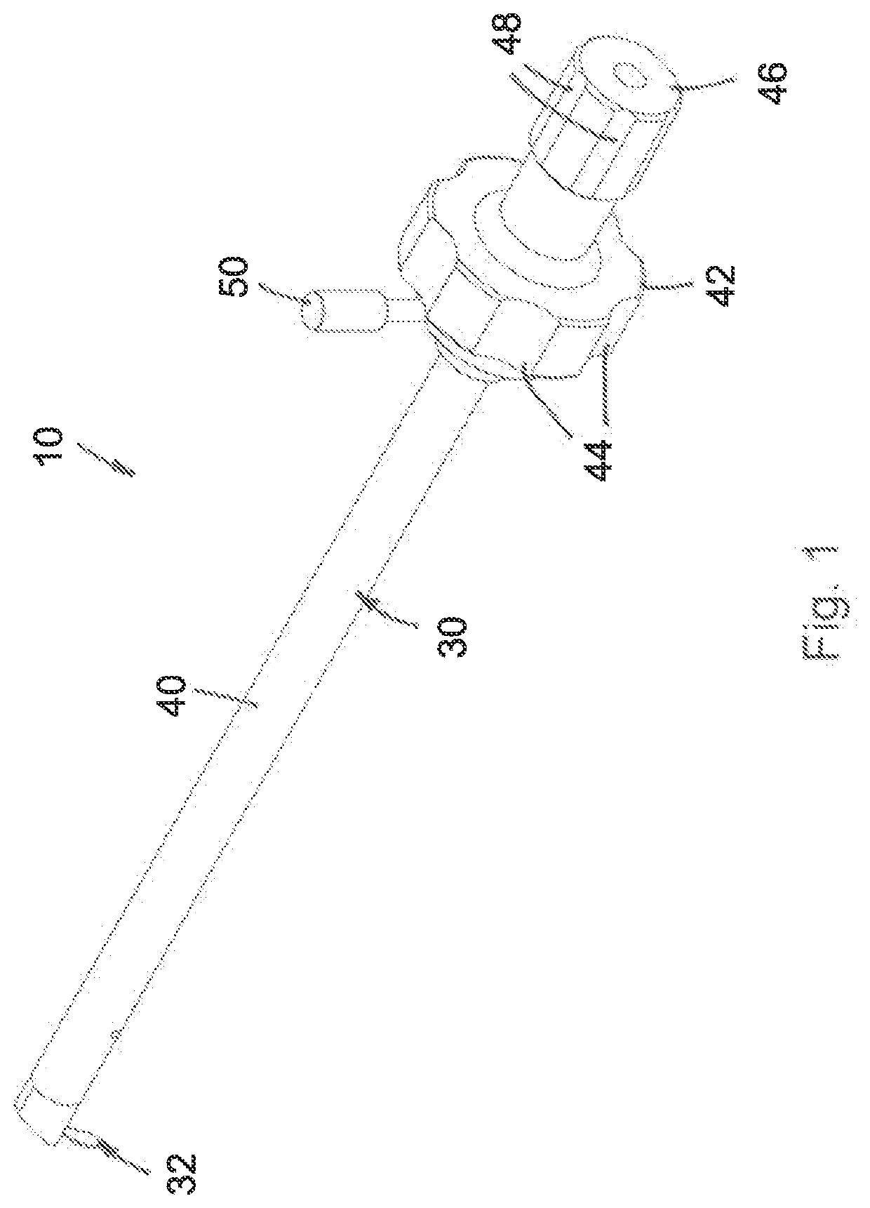
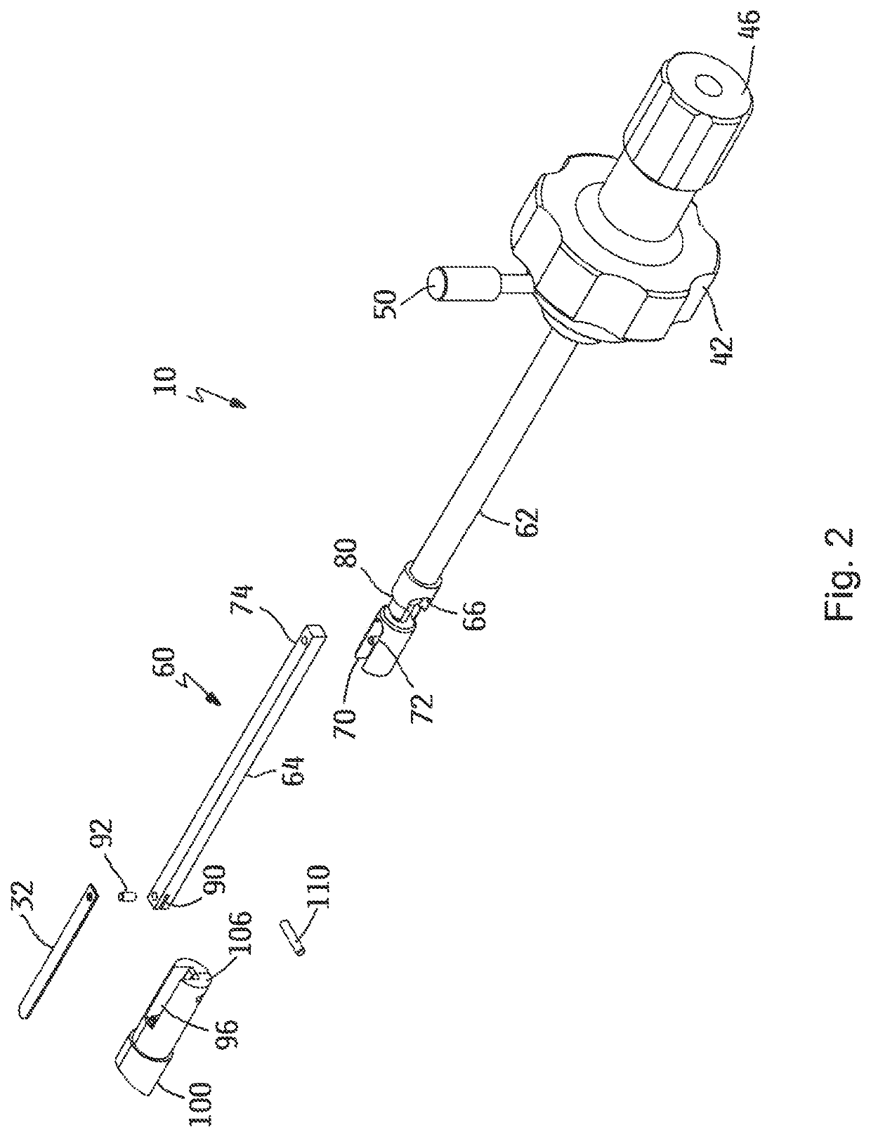
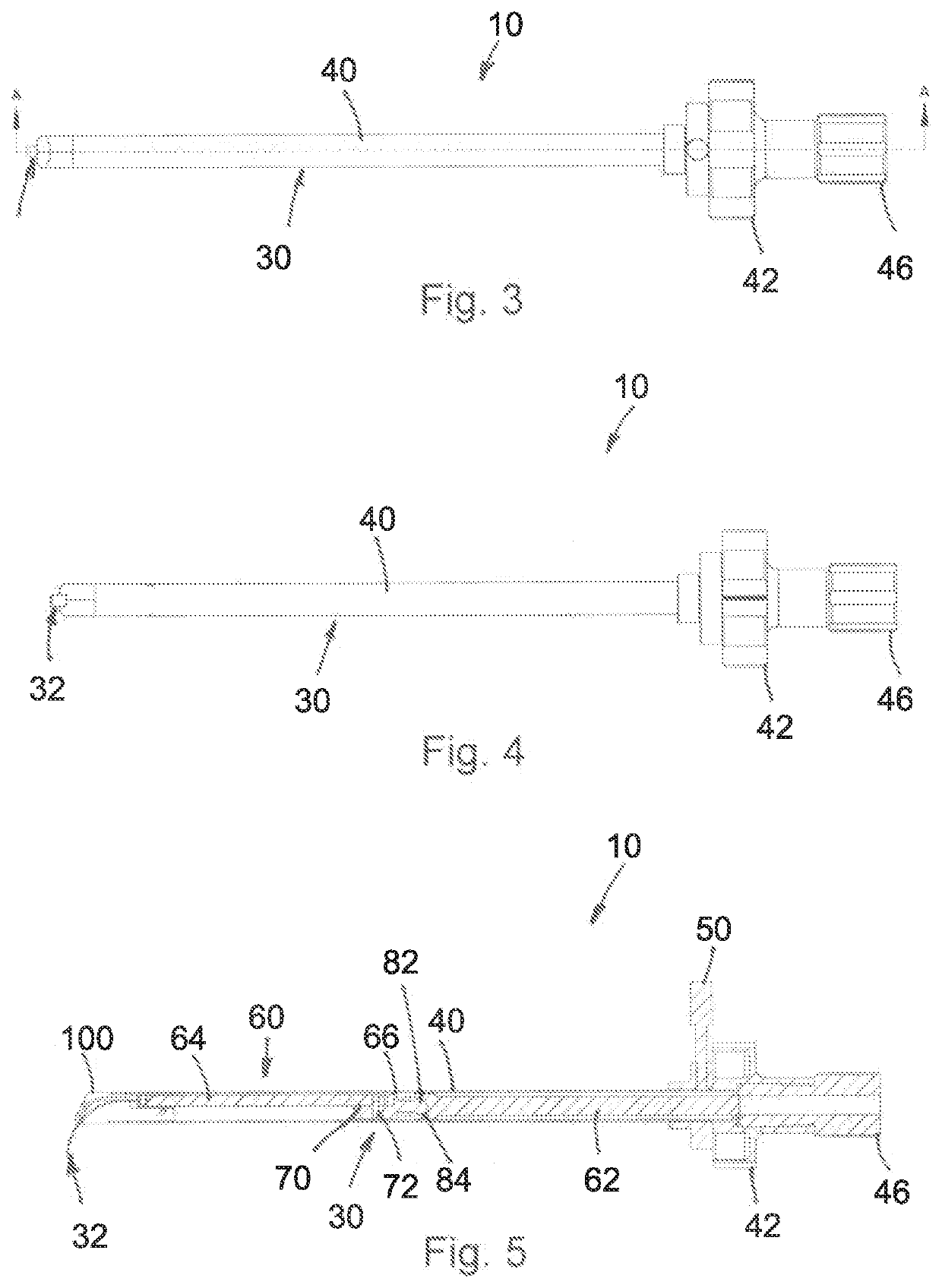
[0082]An embodiment of the invention is directed to an undercutting system 10, such as is illustrated in FIGS. 1-5. The undercutting system 10 may be used for preparing surfaces of the ilium 14 and the sacrum 16 for sacroiliac joint fusion, which are illustrated in FIG. 31. The undercutting system utilizes an aperture 20 formed in the ilium 14 to access a region 22 between the ilium 14 and the sacrum 16.

[0083]In certain embodiments, the aperture 20 may have a diameter of up to about 50 millimeters. In other embodiments, the aperture 20 may have a diameter of between about 5 millimeters and 20 millimeters.

[0084]The undercutting system 10 thereby enables tissue such as cartilage to be removed from the adjacent surfaces of the ilium 14 and the sacrum 16 and for at least a portion of the adjacent surfaces of the ilium 14 and the sacrum 16 to be removed or otherwise disturbed. This procedure may be referred to as preparing bleeding bone surfaces on the ilium 14 and the sacrum 16, which a...


PUM


Abstract

Methods and apparatuses for performing an orthopedic procedure in the sacroiliac region are disclosed. In one form, an aperture is formed that at least partially extends through at least one of an ilium and a sacrum. An undercutting system is inserted into the aperture. The undercutting system includes an insertion apparatus, a probe assembly and a cutting assembly. The probe assembly is moved with respect to the insertion apparatus from a retracted position to an extended position. The probe assembly is manipulated within a joint between the ilium and the sacrum while the probe assembly is in the extended position. The cutting assembly is moved with respect to the insertion apparatus from a retracted position to an extended position. The cutting assembly is manipulated within the joint between the ilium and the sacrum while the cutting assembly is in the extended position to form a fusion region.

Description

CROSS-REFERENCE TO RELATED APPLICATIONS[0001]This application is a continuation of U.S. patent application Ser. No. 16 / 233,598, which was filed on Dec. 27, 2018, which is a continuation of U.S. patent application Ser. No. 15 / 608,705, which was filed on May 30, 2017 and issued as U.S. Pat. No. 10,596,002, which is a continuation of U.S. patent application Ser. No. 14 / 721,753, which was filed on May 26, 2015 and which issued as U.S. Pat. No. 9,662,124, which is a divisional of U.S. patent application Ser. No. 13 / 465,612, which was filed on May 7, 2012 and which issued as U.S. Pat. No. 9,161,763, which claims the benefit of priority from U.S. Provisional Patent Application No. 61 / 610,759, filed Mar. 14, 2012, and U.S. Provisional Patent Application No. 61 / 482,899, filed May 5, 2011, and is a continuation-in-part of U.S. patent application Ser. No. 12 / 938,976, filed on Nov. 3, 2010 and which issued as U.S. Pat. No. 8,348,950, which claims the benefit of priority from U.S. Provisional Pa...

Claims


Application Information

Patent Timeline
Patent Type & Authority Applications(United States)
IPC IPC(8): A61F2/30A61B17/16A61B17/32A61B17/70A61B17/84
CPCA61F2/30988A61B17/1617A61B17/1664A61B17/320016A61B2090/031A61B17/16A61B17/1671A61B17/32002A61B17/84A61B17/7055A61B2017/32006A61B17/1659A61F2002/30995A61B2017/00261A61B2017/0046A61B2017/00867A61B2090/062A61B17/1604A61B17/1608A61B17/1624A61B17/1633A61B2017/00464A61B2017/00469A61B2017/320004A61B2017/320791A61B2017/320008A61B17/3203A61B2017/320012A61B2017/320028A61B2017/320032
Inventor ASSELL, ROBERTCARR, JEREMYDICKHUDT, EUGENEBERG, THOMASBEAUBIEN, BRIAN
Owner SURGALIGN SPINE TECH INC
Learn More