
Rotor and motor comprising same

a rotor and motor technology, applied in the direction of magnetic circuits, magnetic circuits characterised by magnetic materials, magnetic circuit shapes/forms/construction, etc., can solve the problems of limitation in reducing costs and limit the so as to reduce the degree of design freedom of rotors can be improved, and the cost of rotors can be reduced.

Pending Publication Date: 2022-03-03
LG INNOTEK CO LTD
View PDF6 Cites 0 Cited by
  • Summary
  • Abstract
  • Description
  • Claims
  • Application Information

AI Technical Summary

Benefits of technology

The patent describes a rotor structure that reduces costs and improves design flexibility. This is achieved by using magnets made of different materials or by using two magnets with different areas. The second magnet is designed to maintain its magnetic strength. By using different rotor cores and a protrusion, the rotor's performance and assembly accuracy can be improved. Overall, the patent offers a cost-effective solution for creating efficient and reliable rotors.

Problems solved by technology

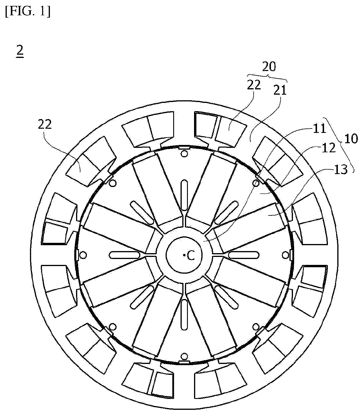
Accordingly, since the shape of the magnet 13 is fixed to a rectangular parallelepiped shape, there is a limitation in a level of design freedom of the rotor 10.
In addition, since the same type of the magnets 13 is used in the rotor 10, there is a limitation in reducing a cost.

Method used


Image

  • Rotor and motor comprising same
  • Rotor and motor comprising same
  • Rotor and motor comprising same

Examples


Embodiment Construction

[0069]Hereinafter, exemplary embodiments of the present invention will be described in detail with reference to the accompanying drawings.

[0070]However, the technical spirit of the present invention is not limited to some embodiments which will be described and may be realized in a variety of different forms, and one or more components of the embodiments may be selectively coupled, substituted, and used to realize the technical spirit within the range of the technical spirit.

[0071]In addition, unless clearly and specifically defined otherwise by context, all terms (including technical and scientific terms) used herein can be interpreted as having customary meanings to those skilled in the art, and meanings of generally used terms, such as those defined in commonly used dictionaries, will be interpreted by considering contextual meanings of the related technology.

[0072]In addition, the terms used in the embodiments of the present invention are considered in a descriptive sense and no...


PUM


Abstract

An embodiment presents a motor comprising: a shaft; a rotor to which the shaft is coupled; and a stator which is disposed at the exterior of the rotor, wherein: the stator comprises a stator core and a coil which is wound around the stator core; the stator core comprises a yoke, a tooth which protrudes from the yoke, and a first groove and a second groove which are formed on the inner surface of the tooth; and distances from the center of the circumferential direction of the tooth to the first groove and the second groove are different from each other. Accordingly, the motor can reduce cogging torque through a design for the grooves disposed to be asymmetrical with reference to the center of the tooth.

Description

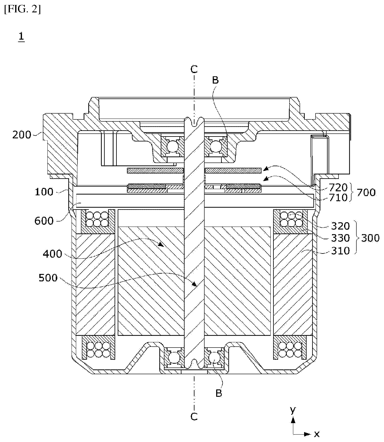
TECHNICAL FIELD[0001]An embodiment relates to a rotor and a motor including the rotor.BACKGROUND ART[0002]Motors are apparatuses configured to convert electrical energy to mechanical energy to obtain rotational forces and are widely used for vehicles, home appliances, industrial machines, and the like.[0003]The motor may include a housing, a shaft, a stator disposed on an inner circumferential surface of the housing, a rotor disposed on the shaft, and the like. In this case, the stator of the motor induces an electrical interaction with the rotor to induce rotation of the rotor.[0004]FIG. 1 is a view illustrating a rotor and a stator of a conventional spoke type motor.[0005]Referring to FIG. 1, a conventional motor 2 may include a rotor 10 and a stator 20. In this case, the motor 2 may be formed as a spoke type. Accordingly, the rotor 10 includes a rotor yoke 11 and rotor teeth 12, and magnets 13 are disposed between the rotor teeth 12. In this case, the magnets 13 are radially disp...

Claims


Application Information

Patent Timeline
Patent Type & Authority Applications(United States)
IPC IPC(8): H02K1/27H02K7/00H02K15/03H02K16/02
CPCH02K1/276H02K16/02H02K15/03H02K7/003H02K1/2773H02K21/16H02K1/30H02K2211/03H02K11/215H02K1/02H02K1/28H02K21/14H02K2213/03
Inventor YANG, JUNG SOO
Owner LG INNOTEK CO LTD
Learn More