
Rotor, motor, and wiper motor

a technology of rotor and wiper, which is applied in the direction of magnetic circuit rotating parts, vehicle cleaning, shape/form/construction, etc., can solve the problems of increasing operating noise, permanent magnet rattle, adhesive peeling, etc., and achieves the suppression of the increase in operating noise and deterioration in the rotor characteristics, the reduction of the radial wall thickness of the permanent magnet, and the narrowing of the circumferential movement range of the permanent magn

Pending Publication Date: 2022-02-24
MITSUBA CORP
View PDF0 Cites 1 Cited by
  • Summary
  • Abstract
  • Description
  • Claims
  • Application Information

AI Technical Summary

Benefits of technology

The invention aims to prevent damage to the permanent magnet and reduce noise and deterioration of rotor characteristics while also reducing the material cost of the permanent magnet. The technical effects of the invention include reducing the stress applied to the permanent magnet by avoiding forcible arrangement of the permanent magnet on the outer circumferential surface of the rotor core, preventing damage to the permanent magnet through the use of backlash between the salient pole and the permanent magnet, and reducing the material cost of the permanent magnet by reducing the radial wall thickness of the permanent magnet.

Problems solved by technology

Here, as in the related art described above, if the circumferential width of the permanent magnet is set to be smaller than the width between circumferentially adjacent salient poles, when the permanent magnet is fixed to the rotor core by the magnet cover, the permanent magnet may rattle by the gap between the permanent magnet and the salient poles and increase the operating noise.
Even if the permanent magnet is fixed to the rotor core using an adhesive, the adhesive may peel off and the permanent magnet may rattle.
In addition, the rotor characteristics may deteriorate due to displacement of the permanent magnet.
Furthermore, as in the related art described above, if the radial wall thickness of the permanent magnet is gradually increased toward the circumferential center, there is a problem that the material cost for the permanent magnet increases.

Method used


Image

  • Rotor, motor, and wiper motor
  • Rotor, motor, and wiper motor
  • Rotor, motor, and wiper motor

Examples


Embodiment Construction

[0021]Next, an embodiment of the invention will be described with reference to the drawings.

(Wiper Motor)

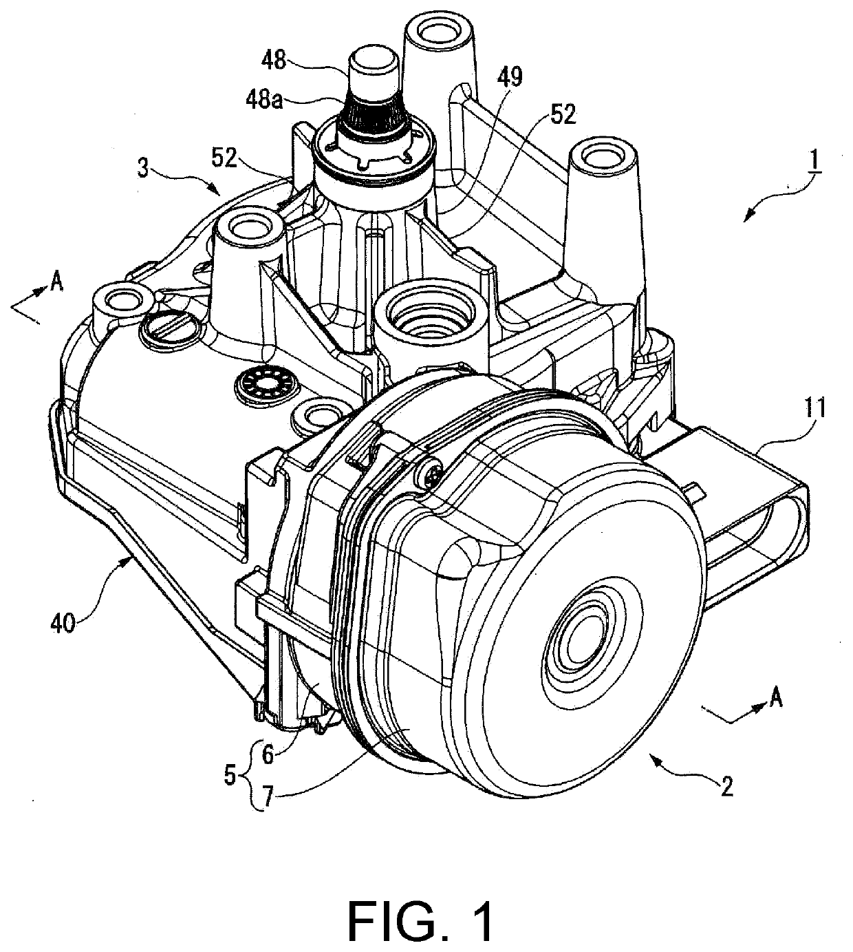
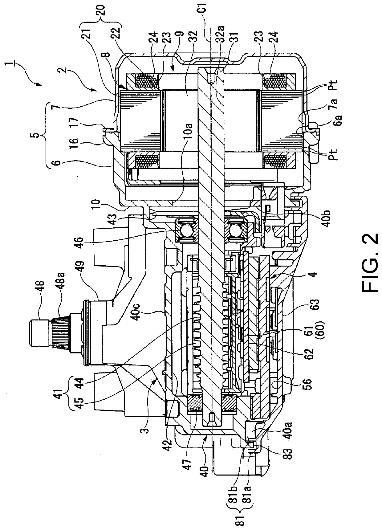
[0022]FIG. 1 is a perspective view of a wiper motor 1. FIG. 2 is a cross-sectional view taken along the line A-A of FIG. 1. As shown in FIG. 1 and FIG. 2, the wiper motor 1 serves as a drive source for a wiper mounted on a vehicle, for example. The wiper motor 1 includes a motor part (motor) 2, a deceleration part 3 that decelerates and outputs the rotation of the motor part 2, and a controller part 4 that controls the drive of the motor part 2. In the following description, the term “axial direction” refers to the direction of a rotational axis C1 of a shaft 31 of the motor part 2, the term “circumferential direction” refers to the circumferential direction of the shaft 31, and the term “radial direction” refers to the radial direction of the shaft 31.

(Motor Part)

[0023]The motor part 2 includes a motor case 5, a substantially cylindrical stator 8 housed in the motor case 5, and ...


PUM


Abstract

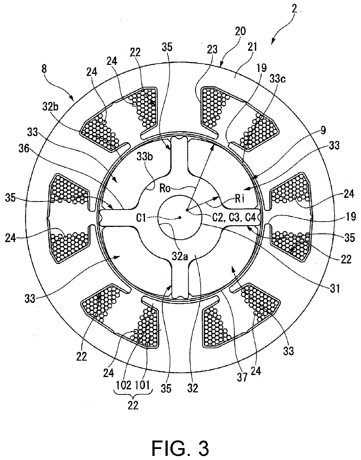
Provided are a rotor, a motor, and a wiper motor. An arc center of an outer circumferential surface of a rotor core and an arc center of an inner circumferential surface of a permanent magnet are off-centered radially outward from a rotational axis, with the circumferential center disposed on the radially outermost side. An angle formed by salient pole side surfaces facing each other of circumferentially adjacent two salient poles is equal to an angle formed by magnet side surfaces on both sides circumferentially of the permanent magnet. When the distance between the outer circumferential surface of the rotor core and the radially outermost end of the salient poles is Lt, and the distance between the inner circumferential surface of the permanent magnet and the radially outermost end of the magnet side surfaces is Lme, the distances Lt, Lme are set such that the relationship Lme<Lt is satisfied.

Description

BACKGROUNDTechnical Field[0001]The invention relates to a rotor, a motor, and a wiper motor.Description of Related Art[0002]Conventionally, a SPM (surface permanent magnet) type rotor is known, in which a plurality of permanent magnets for a magnetic field are arranged side by side in the circumferential direction on an outer circumferential surface of a rotor core. Among SPM type rotors of this type, a so-called inset type rotor is also known, which includes a plurality of salient poles protruding radially outward from the outer circumferential surface of the rotor core and arranged between circumferentially adjacent permanent magnets. In this type of inset type rotor, the rotor core and the salient poles are made of a magnetic material. Since the protruding direction of the salient poles of the rotor core is radially outward, it is a direction that the interlinkage magnetic flux generated by a coil of a stator tends to flow. In addition, the salient poles generate a reluctance tor...

Claims


Application Information

Patent Timeline
Patent Type & Authority Applications(United States)
IPC IPC(8): H02K1/27H02K7/116H02K21/16B60S1/08
CPCH02K1/278H02K7/1166H02K29/03B60S1/08H02K21/16H02K7/116H02K2213/03
Inventor OHORI, RYO
Owner MITSUBA CORP
Learn More