
Delay control device and tunable delay device

a delay control and delay technology, applied in the direction of pulse manipulation, pulse technique, electrical apparatus, etc., can solve the problems of low data output efficiency, the overall performance of the related circuit is still not improving, and the overall performance of the related circuit is declining, so as to improve the overall operating performance of the related circui

Active Publication Date: 2022-02-10
WINBOND ELECTRONICS CORP
View PDF0 Cites 0 Cited by
  • Summary
  • Abstract
  • Description
  • Claims
  • Application Information

AI Technical Summary

Benefits of technology

The invention proposes a delay control device and a tunable delay device that can be used to control the delay time of a circuit. These devices are designed to be used with an external clock signal, which helps to avoid the impact of variations in voltage and temperature. This design also allows for compensating for different delay times that may occur in different parts of the circuit. By optimizing the delay time of the circuit, these devices improve the overall performance of the circuit and help to achieve better results.

Problems solved by technology

However, such a delay circuit still cannot improve the problem of inconsistent delay times for circuits in different locations.
This non-ideal characteristic will cause the overall performance of the related circuit to decline.
Thus, it is necessary to set the specification of the delay time to be longer, resulting in low-efficiency of data output.

Method used


Image

  • Delay control device and tunable delay device
  • Delay control device and tunable delay device
  • Delay control device and tunable delay device

Examples


Embodiment Construction

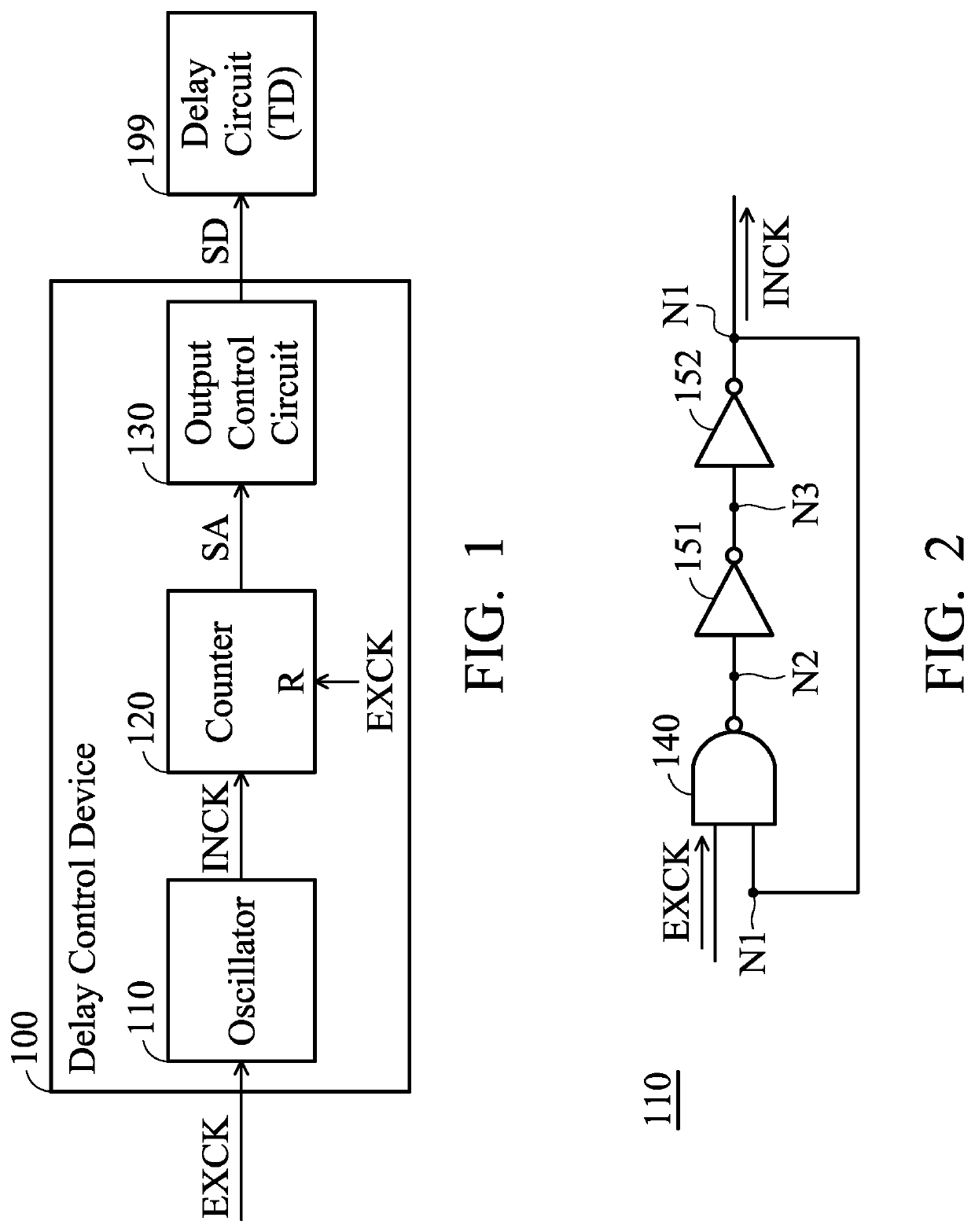
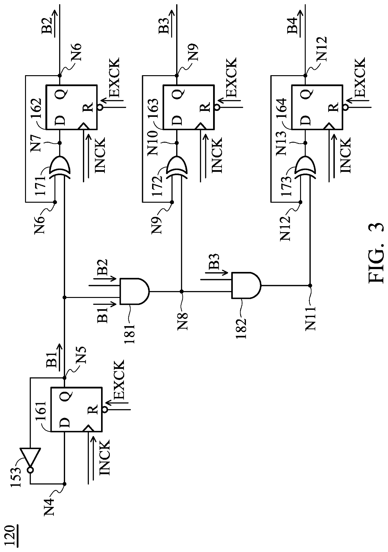
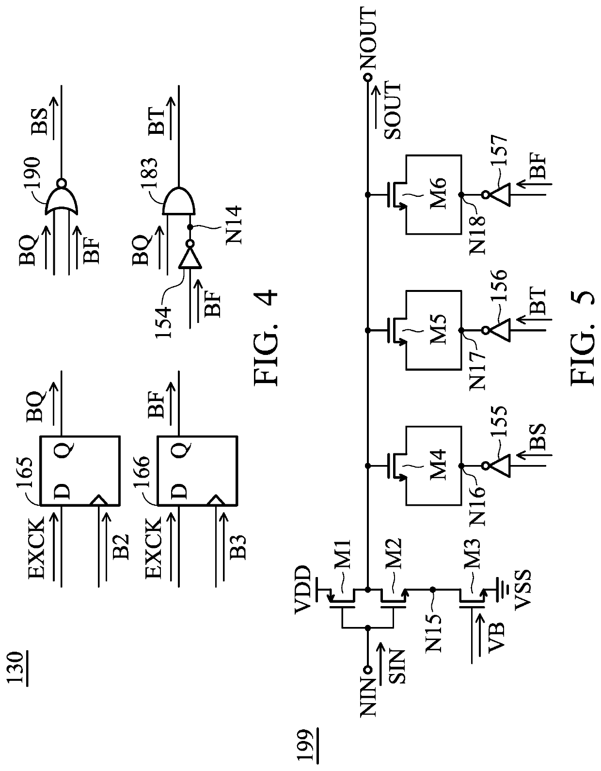
[0016]FIG. 1 is a diagram of a delay control device 100 according to an embodiment of the invention. The delay control device 100 may be applied in an electronic device, such as a mobile device or a memory device, but it is not limited thereto. As shown in FIG. 1, the delay control device 100 controls a delay circuit 199 and includes an oscillator 110, a counter 120, and an output control circuit 130. The oscillator 110 generates an internal cock signal INCK according to an external clock signal EXCK. It should be noted that the frequency and period of the external clock signal EXCK are predetermined and not changed by PVT variations of relative circuitry. The counter 120 generates an accumulative signal SA according to the internal clock signal INCK. The counter 120 is selectively reset by the external clock signal EXCK. For example, the accumulative signal SA of the counter 120 may be reset to 0 at every falling edge or every rising edge of the external clock signal EXCK. The outp...


PUM


Abstract

A delay control device for controlling a delay circuit includes an oscillator, a counter, and an output control circuit. The oscillator generates an internal clock signal according to an external clock signal. The counter generates an accumulative signal according to the internal clock signal. The counter is selectively reset by the external clock signal. The output control circuit generates a delay indication signal according to the accumulative signal. The delay time of the delay circuit is adjusted according to the delay indication signal.

Description

CROSS REFERENCE TO RELATED APPLICATIONS[0001]This application claims priority of Taiwan Patent Application No. 109126719 filed on Aug. 6, 2020, the entirety of which is incorporated by reference herein.BACKGROUND OF THE INVENTIONField of the Invention[0002]The disclosure generally relates to a delay control device, and more specifically, to a delay control device for optimizing a delay time.Description of the Related Art[0003]Since there are variations of process, voltage, and temperature (hereinafter referred to as “PVT variations”) in general delay circuits, the delay time that is generated has obvious variations. To solve this problem, a delay circuit that can sense PVT variations is proposed. However, such a delay circuit still cannot improve the problem of inconsistent delay times for circuits in different locations. This non-ideal characteristic will cause the overall performance of the related circuit to decline. For example, in a memory device, if a conventional delay circui...

Claims


Application Information

Patent Timeline
IPC IPC(8): H03K5/131H03K5/135
CPCH03K5/131H03K2005/00058H03K5/135H03K5/133
Inventor CHOU, YEN-YU
Owner WINBOND ELECTRONICS CORP
Learn More