
Fluid-solid coupling numerical simulation method for evaluating effect of wellbore strengthening in fractured formation

a fracture formation and fluid-solid coupling technology, applied in the field of oil and gas exploration, can solve the problems of large loss of drilling fluid materials, long non-production time, and significant loss of drilling fluid

Active Publication Date: 2022-01-13
SOUTHWEST PETROLEUM UNIV
View PDF0 Cites 7 Cited by
  • Summary
  • Abstract
  • Description
  • Claims
  • Application Information

AI Technical Summary

Benefits of technology

The present invention provides a method for strengthening wellbores in fractured formations. The method takes into account complex flow forms and deformation characteristics, which allows for more accurate and effective design of parameter settings and evaluation of wellbore strengthening. The method can serve as a theoretical guide for designing and evaluating wellbore strengthening.

Problems solved by technology

These formations often resulted in a considerable drilling fluid loss.
Lost circulation not only causes large loss of drilling fluid materials and long non-production time, but also easily induces downhole failures such as wellbore instability, blowout and sticking.
Furthermore, lost circulation can also cause immeasurable damage to reservoirs.
ing. Although the above models and methods provide certain theoretical guidance for the design of the wellbore strengthening scheme, all are of some limitat
dered. However, the conventional analytical or numerical models were established based on the constant pressure boundary condition, and the influence of plugging zone permeability and the interaction between the plugging zone and the fracture surfaces are rarely consi
dered. As a result, the prediction of the wellbore strengthening effect is distorted, and thus providing insufficient theoretical basis for the plugging scheme for the wellbore strengt

Method used


Image

  • Fluid-solid coupling numerical simulation method for evaluating effect of wellbore strengthening in fractured formation
  • Fluid-solid coupling numerical simulation method for evaluating effect of wellbore strengthening in fractured formation
  • Fluid-solid coupling numerical simulation method for evaluating effect of wellbore strengthening in fractured formation

Examples


Embodiment Construction

[0041]In order to clarify the purpose, technical solutions and advantages of the embodiments of the present invention, the technical solutions of the embodiments of the present invention will be clearly and completely described below with the accompanying drawings. The described embodiments are only a few embodiments of the present invention rather than all. All other embodiments, which can be derived by those skilled in the art from the described embodiments of the present invention without any inventive step, are within the protection scope of the present invention.

[0042]Unless otherwise defined, technical or scientific terms used herein shall have the ordinary meaning as understood by those skilled in the art. The use of “include”, “comprise”, and the like, in the present invention is intended to mean that the elements or items listed before that word include the elements or items listed after that word, and their equivalents, without excluding other elements or items. The words ...


PUM


Abstract

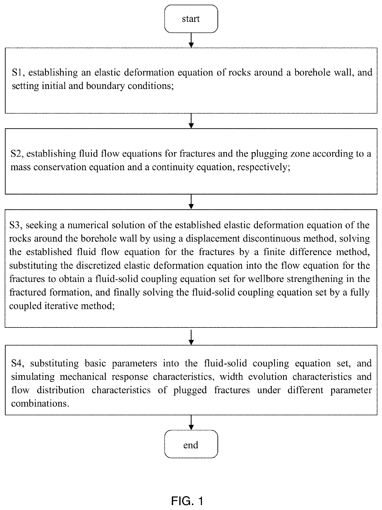
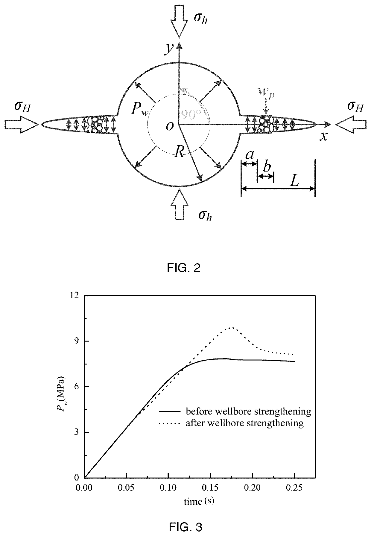
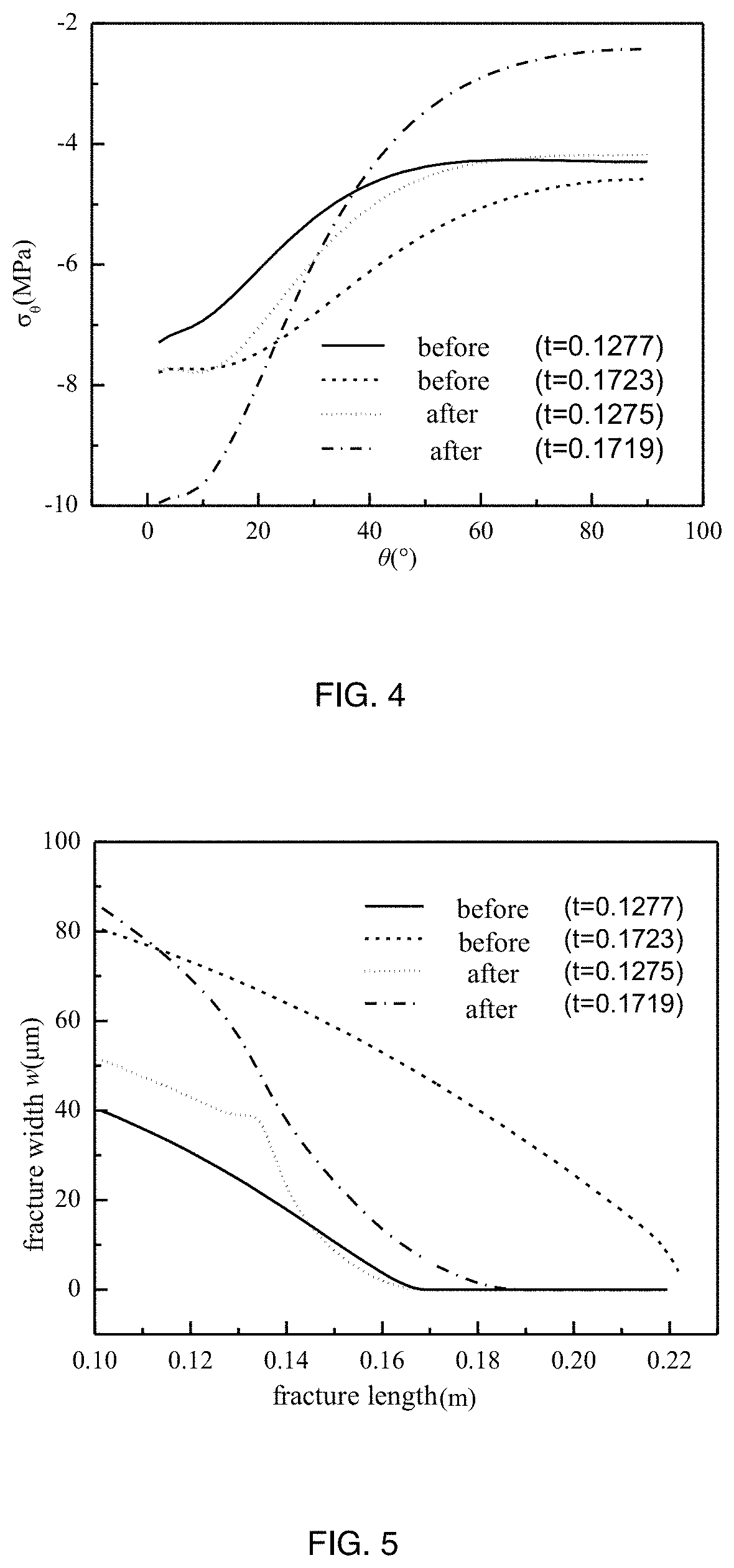
A fluid-solid coupling numerical simulation method for evaluating the effect of wellbore strengthening in a fractured formation includes steps of: establishing an elastic deformation equation of rocks around the wellbore; establishing and solving the fluid flow equations within fractures and plugging zone, respectively; substituting the discretized elastic deformation equation of the rocks around the borehole wall into the fluid flow equations of fractures to obtain a fluid-solid coupling equation set for wellbore strengthening in a fractured formation; and finally solving the fluid-solid coupling equation set; and substituting basic parameters into the fluid-solid coupling equation set, and simulating mechanical response characteristics, width evolution characteristics and flow distribution characteristics of plugged fractures under different parameter combinations. The present invention systematically considers the complex flow states of plugged fractures during wellbore strengthening, as well as the deformation and seepage characteristics plugging zone under multi-force coupling.

Description

CROSS REFERENCE OF RELATED APPLICATION[0001]The present invention claims priority under 35 U.S.C. 119(a-d) to CN 202010928300.1, filed Sep. 7, 2020.BACKGROUND OF THE PRESENT INVENTIONField of Invention[0002]The present invention relates to a technical field of oil and gas exploration, and more particularly to a fluid-solid coupling numerical simulation method for evaluating an effect of wellbore strengthening in a fractured formation.Description of Related Arts[0003]With the global oil and gas exploration and development transiting to deep formations and unconventional oil and gas resources, the occurrence of drilling into broken formation, fractured formation and formation with complex pressure system is greatly increased. These formations often resulted in a considerable drilling fluid loss. Lost circulation not only causes large loss of drilling fluid materials and long non-production time, but also easily induces downhole failures such as wellbore instability, blowout and sticki...

Claims


Application Information

Patent Timeline
Patent Type & Authority Applications(United States)
IPC IPC(8): G06F30/28E21B47/00
CPCG06F30/28G06F2111/10E21B2200/20E21B47/00G06F30/23G06F2113/08G06F2119/14E21B21/003
Inventor LIU, YANGMA, TIANSHOUCHEN, PINGXIANG, XINGYUNZOU, JIAYAN
Owner SOUTHWEST PETROLEUM UNIV
Learn More