Adjustable t-square

a t-square and adjustment technology, applied in the direction of mechanical transmission signalling system, instruments, using mechanical means, etc., can solve the problems of increased costs, waste of wood and material, and difficult to even the most seasoned woodworker

Active Publication Date: 2022-01-13
WOODPECKERS LLC
View PDF0 Cites 7 Cited by
  • Summary
  • Abstract
  • Description
  • Claims
  • Application Information

AI Technical Summary

Problems solved by technology

A wrong cut leads to wasted wood and material which in turn increases costs.
Many times, a woodworker will use a tape measurer and a scrap piece of wood, presenting a difficult challenge to even the most seasoned of woodworkers to insure accuracy.
Specifically, when doing angled l

Method used


Image

  • Adjustable t-square
  • Adjustable t-square
  • Adjustable t-square

Examples


Embodiment Construction

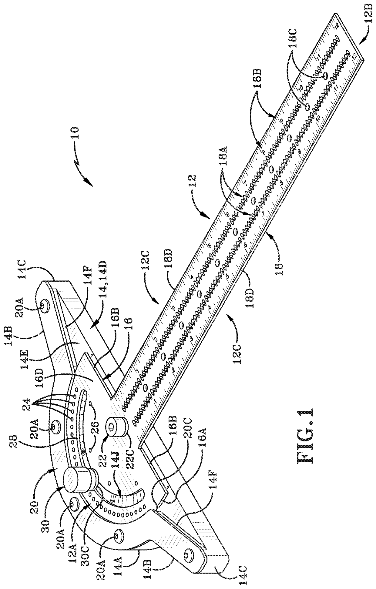
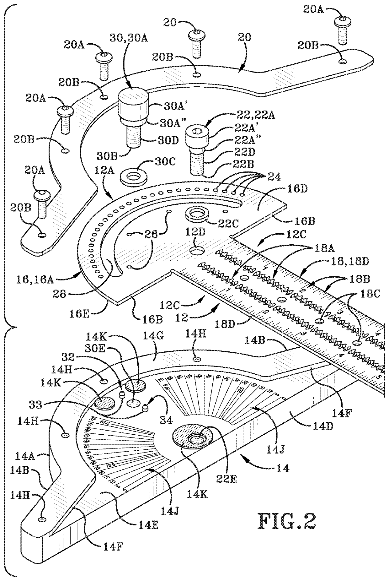
[0020]A new adjustable T-square apparatus 10 and method of operation thereof is depicted in the present disclosure and throughout FIGS. 1-9. The disclosure focuses on improved adjustable T-square apparatus that allows for highly accurate measurements and operation thereof, as will be discussed hereafter.

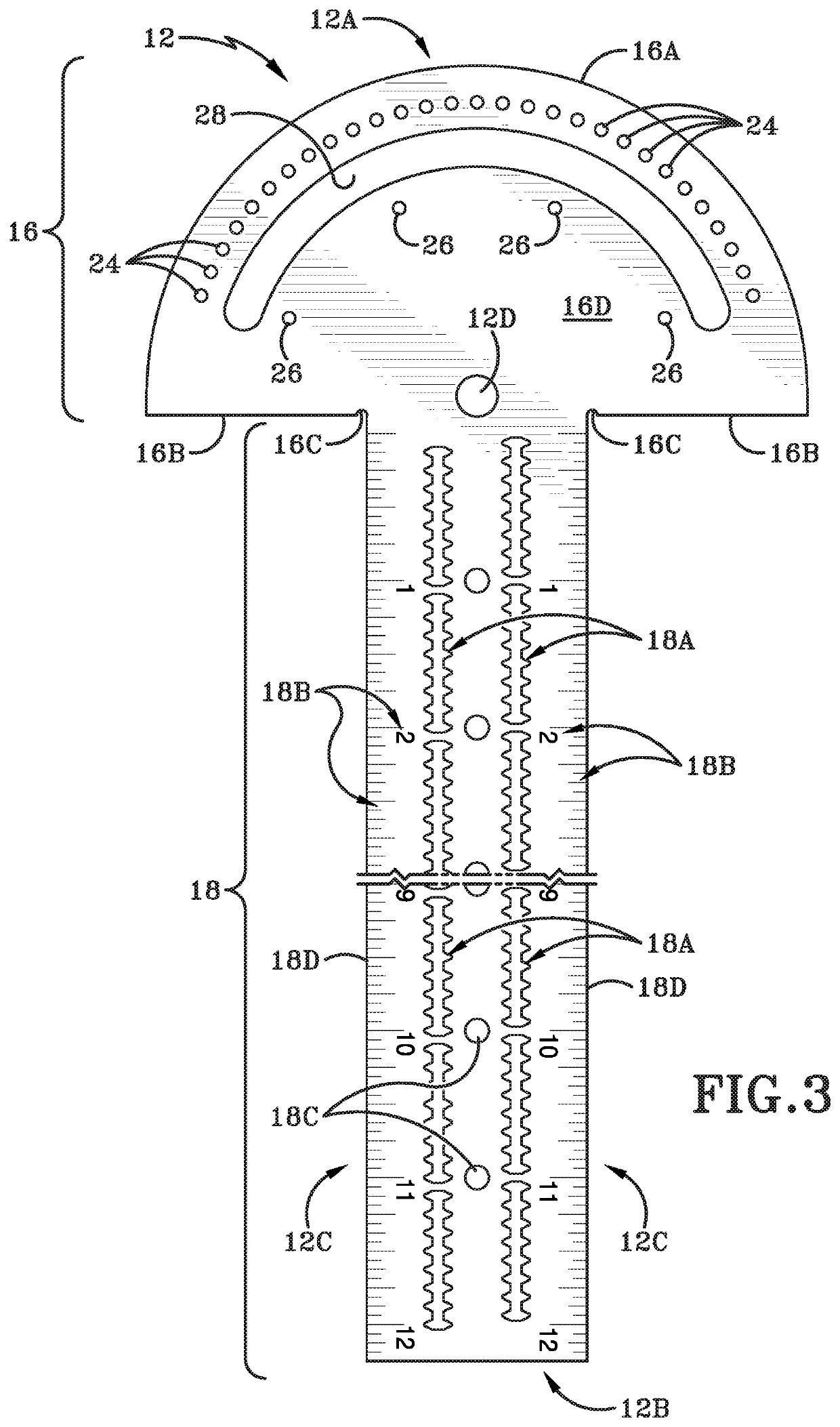
[0021]Referring specifically to FIG. 1, a top left isometric view of the exemplary adjustable T-square apparatus 10 is shown. The T-square 10 has a body and includes generally a ruler portion 12 and a head portion 14. The ruler portion 12 has a first end 12A that is generally arcuate in nature and a second end 12B longitudinally disposed to the first end 12B. The ruler portion 12 is further bound by a pair of edges 12C that extend parallel to one another. The ruler portion 12 is generally broken into two sections, a first portion 16 or a semi-circular head portion 163) and a second portion 18 or an arm portion 18, as will be discussed later.

[0022]The head portion 14 has a body define...


PUM


Abstract

An adjustable T-square device and method of use is shown and described herein. The adjustable T-square has a plurality of apertures with at least one locking detent to set precise angles. The adjustable T-square has a locking pin to further engage a ruler portion to a head portion to minimize error when using the device.

Description

TECHNICAL FIELD[0001]Generally, the disclosure relates to an adjustable T-square with a head portion and a ruler portion. Particularly, the disclosure relates to an adjustable T-square with a head portion with indicia of angles and at least one locking detent. Specifically, the disclosure relates to an adjustable T-square with at least one locking detent with a plurality of angle apertures and a locking pin to secure and allow for precise angles to be drawn by a user.BACKGROUNDBackground Information[0002]T-squares are used commonly as a guide for drawing horizontal lines. The name T-square comes from the tools resemblance to the capital letter T in the English language. Generally, T-squares consist of two components, the short shaft called the head or stock and the long shaft called a blade. The inside edge of the head or stock of the T-square is placed against the working edge of the surface desired to be drawn on. The off-hand of the user may then be moved to secure the T-square a...

Claims


Application Information

Patent Timeline
IPC IPC(8): G01B3/00G01B3/04G01B3/56G08B7/00
CPCG01B3/004G08B7/00G01B3/566G01B3/04G01B3/56G08B7/02
Inventor CROSS, STEVEN CHARLES
Owner WOODPECKERS LLC
Why Eureka
Try Eureka