
On-ear electroencephalographic monitoring device

a monitoring device and electroencephalography technology, applied in the field of electroencephalographic monitoring devices, can solve the problems of lack of accuracy, inability to diagnose the type of seizure in full confidence, and the act of recalling negative feelings may aggravate the mental status of patients, so as to limit the overall cross-sectional dimension of the device, enhance user engagement in brainwave detection, and ensure the effect of accuracy

Pending Publication Date: 2022-01-06
CEPHALGO SAS
View PDF7 Cites 3 Cited by
  • Summary
  • Abstract
  • Description
  • Claims
  • Application Information

AI Technical Summary

Benefits of technology

The invention relates to a flexible and thin material that is overmolded onto a flexible printed circuit (FPC) and acts as a substrate for housing sensors. This material helps limit the size of the device. Compared to existing devices, the thickness of the sensor and its electrical connection are significantly reduced, making the device slimmer and more flexible, which is beneficial for a portable device. The use of an FPC makes the device lighter, comfortable, and inconspicuous when in use. The technical effect is improved user engagement on brainwave detection.

Problems solved by technology

This means that unless the patients experience a seizure during an EEG recording, the doctor cannot diagnose the type of seizure in full confidence.
It often lacks accuracy as it relies on memories to recall the moods throughout a day.
Furthermore, the act of recalling negative feelings may aggravate the mental status of the patient.
However, the existing prior art EEG devices have bulky and obvious structures that can be worn exclusively in laboratories or in private.
One issue with such systems is that the EEG monitoring devices described in the prior art are not size adjustable, and therefore may not be appropriate for all users.
Another issue with such systems is that many of the EEG monitoring devices described in the prior art are bulky and thus impractical for wearing inconspicuously throughout the duration of a user's day.

Method used


Image

  • On-ear electroencephalographic monitoring device
  • On-ear electroencephalographic monitoring device
  • On-ear electroencephalographic monitoring device

Examples


Embodiment Construction

[0024]The description of the invention provided herein is for exemplary purposes and is not intended to limit the invention to any of the embodiments described herein. The figures used to support this specification are not intended to limit the invention to any specific shape, size, aesthetic design, or any other feature or property of the invention. The claimed invention is best understood by the appended claims.

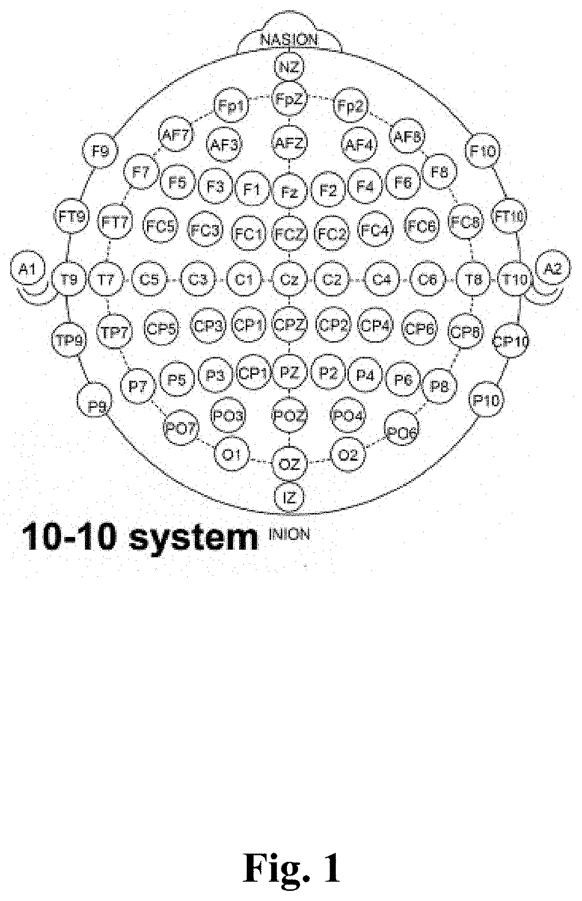
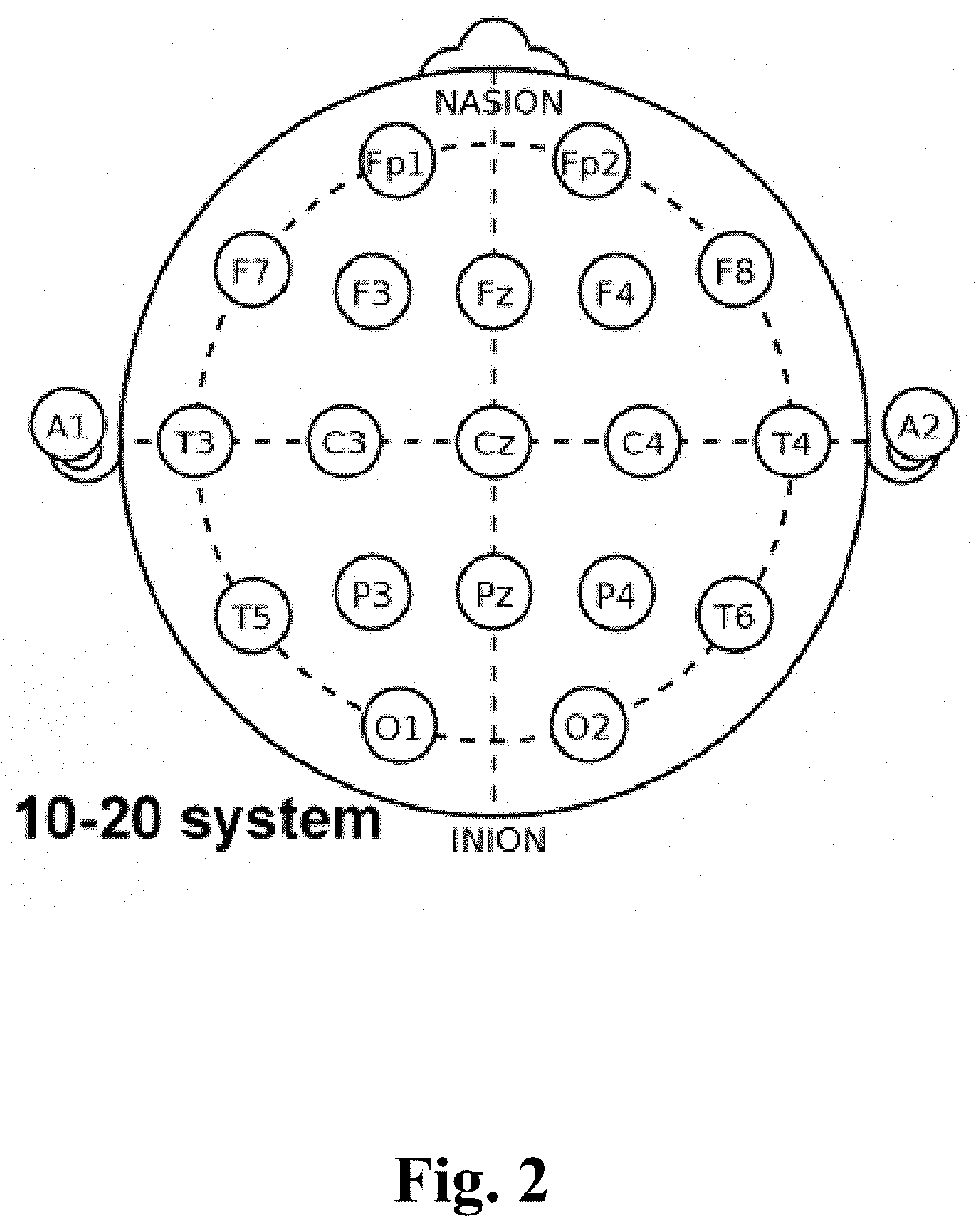
[0025]There are two systems of standardized EEG locations which are the 10-10 EEG system and the traditional 10-20 EEG system. FIG. 1 illustrates the placement of electrodes (sensors) on a user's head in the 10-10 EEG system which has been referred to in the present invention. FIG. 2 illustrates the placement of electrodes (sensors) on a user's head in the 10-20 EEG system.

[0026]FIG. 1 illustrates a 10-10 system which is internationally recognized and ensures the placement of EEG sensors to be standardized for further analysis. The 10-10 system of FIG. 1 is derived by modif...


PUM


Abstract

Embodiments of the present invention (herein referred to simply as “the invention”) comprise an EEG monitoring device worn on or around a user's ears. In some embodiments of the invention, the device comprises a flexible printed circuit containing EEG sensors, skin adhesives or adhesive sensors, and a flexible extension to position the sensor adjusting the user's head size. The device may be designed so that when worn by a user, the sensors are placed at specific points on a user's head in order to accurately capture electroencephalography signals. Said specific points may be one or more points of a 10-10 EEG system. The EEG sensors may comprise or may be made of an adhesive material.

Description

[0001]This patent application claims the benefit of priority of U.S. Provisional Application No. 63 / 048,144 entitled “On-Ear (EEG) Electroencephalography Monitoring Device” filed Jul. 5, 2020, which is hereby incorporated herein by reference in its entirety.BACKGROUND OF INVENTION[0002]The present invention, herein referred to as “the invention,” relates to devices for monitoring, detecting, and processing electroencephalographic (EEG) signals of the human brain. More specifically, the invention discloses an instant and discrete EEG monitoring device or adapter that can be worn on or around a user's ears.[0003]Generally speaking, electroencephalography is a monitoring method that records the electrical activity of the brain. Electroencephalography comprises measuring the brainwaves noninvasively via electrodes / sensors placed on the scalp and helps to establish an accurate diagnosis of brain activity. In neurology, one of the common diagnostic applications of electroencephalography i...

Claims


Application Information

Patent Timeline
Patent Type & Authority Applications(United States)
IPC IPC(8): A61B5/291A61B5/257A61B5/00A61B5/31A61B5/369
CPCA61B5/291A61B5/257A61B5/0006A61B2560/04A61B5/369A61B5/6817A61B5/31A61B5/6815A61B5/6822A61B5/7214
Inventor CHIANG, HSIN-YIN
Owner CEPHALGO SAS
Learn More