Ureteral bypass devices and procedures

a technology of ureteral bypass and bypass device, which is applied in the direction of medical devices, wound drains, other medical devices, etc., can solve the problems of inability to achieve long-term use, and major ureteral obstruction

Pending Publication Date: 2021-12-30
WEISSE CHARLES WINSTON +1
View PDF9 Cites 1 Cited by
  • Summary
  • Abstract
  • Description
  • Claims
  • Application Information

AI Technical Summary

Benefits of technology

The invention is a device that can be used to treat different causes of ureteral obstruction, regardless of the patient's size or species. It can be placed subcutaneously and has a port for testing, sampling, and flushing. The device can be indwelling for extended periods of time, allowing for the urinary system to grow in children with anatomical anomalies before considering more dramatic surgeries. The invention has a relatively large internal reservoir for fluids and medications, which can be introduced through the entry site of the port. Overall, the invention has the advantage of being suitable for a wide range of causes of ureteral obstruction and can provide long-term treatment without the need for surgery or discomfort to the patient.

Problems solved by technology

Ureteral obstructions are a major surgical and endourological problem in both human and veterinary medicine.
Unfortunately, situations arise, particularly in small pediatric and veterinary patients, in whom ureteral decompression is necessary but traditional surgery or endourological procedures are associated with excessive morbidity or mortality, are impossible due to the size or anatomy, or are contraindicated.
Placement of an externalized percutaneous nephrostomy tube is also possible in veterinary and pediatric patients for in-hospital stabilization but is not feasible for long-term use.
Major disadvantages associated with long-term use include the need for regular catheter exchanges, the risk of urinary tract infections, urinary leakage and catheter dislodgement, social embarrassment, discomfort, and an impaired quality of life reported for patients.
However, these devices remain promising when all other traditional options have failed.

Method used


Image

  • Ureteral bypass devices and procedures
  • Ureteral bypass devices and procedures
  • Ureteral bypass devices and procedures

Examples


Embodiment Construction

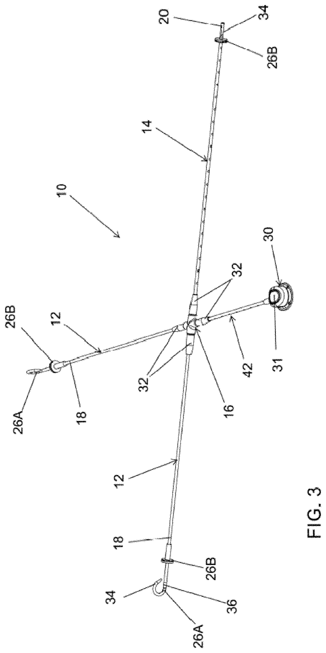
[0017]The intended purpose of the following detailed description of the invention and the phraseology and terminology employed therein is to describe what is shown in the drawings, which include the depiction of one or more nonlimiting embodiments of the invention, and to describe certain but not all aspects of the embodiment(s) depicted in the drawings. The following detailed description also identifies certain but not all alternatives of the depicted embodiment(s). Therefore, the appended claims, and not the detailed description, are intended to particularly point out subject matter regarded as the invention, including certain but not necessarily all of the aspects and alternatives described in the detailed description.

[0018]The embodiments depicted in the drawings will be referred to as ureteral bypass devices (UBD) that are capable of treating causes of ureteral obstruction. The devices can be used in humans (children and adults) and animals, regardless of etiology, species, or ...


PUM


Abstract

Ureteral bypass devices and procedures for performing internalized urinary diversions within patients. Such a procedure includes implanting a first catheter and securing a distal end of the first catheter within the renal pelvis or ureter of a patient, implanting a cystostomy catheter through and securing a distal end of the cystostomy catheter within the urinary bladder of the patient, fluidically connecting proximal ends of the first and cystostomy catheters to an adapter, and then subcutaneously implanting a sampling / flushing port and fluidically connecting a proximal end of the sampling / flushing port to the adapter via a third catheter to yield an artificial ureteral bypass device, in which the first and cystostomy catheters are fluidically connected together and fluidically connected to the subcutaneously-placed sampling / flushing port.

Description

CROSS REFERENCE TO RELATED APPLICATIONS[0001]This application claims the benefit of U.S. Provisional Application No. 63 / 043,270 filed Jun. 24, 2020, the contents of which are incorporated herein by reference.BACKGROUND OF THE INVENTION[0002]The present invention generally relates to devices and procedures suitable for treating patients having ureteral obstructions or the like. More particularly, this invention relates to a ureteral bypass device and procedures for implanting the device, for example, by placing the device under the skin (subcutaneously) or within the abdominal cavity (intra-abdominally) of a patient. The device utilizes catheters and locking / retention mechanisms adapted to retain distal ends of the catheters within the renal pelvis and urinary bladder to avoid inadvertent dislodgement, as well as provide a seal to the kidney and bladder tissues to prevent urine leakage after device placement. The device further includes a port and reservoir that enable and facilitate...

Claims


Application Information

Patent Timeline
Patent Type & Authority Applications(United States)
IPC IPC(8): A61M25/00A61M39/02
CPCA61M25/0017A61M39/02A61M2202/0496A61M2210/1089A61M2039/0202A61M39/0208A61M2205/04A61M25/04A61M27/002A61M2210/1078A61M27/008
Inventor WEISSE, CHARLES WINSTONBERENT, ALLYSON CORTNEY
Owner WEISSE CHARLES WINSTON
Why Eureka
Try Eureka