
Calibration of an optical detector

a technology of optical detectors and calibration methods, applied in the field of smoke detectors, can solve the problems of cumbersome process, time-consuming, and inability to fully automate the process

Active Publication Date: 2021-12-02
CARRIER CORP
View PDF0 Cites 2 Cited by
  • Summary
  • Abstract
  • Description
  • Claims
  • Application Information

AI Technical Summary

Benefits of technology

The patent describes a method for calibrating an optical detector by using a calibration material attached to its surface. The calibration material can be a film or particles that create a known obscuration, which is compared to the detector's readings to determine its parameters. The calibration material can be applied using an adhesive or by positioning it within the detector's sensing volume. The technical effect of this method is that it allows for accurate calibration of the optical detector without interfering with its operation.

Problems solved by technology

This process is cumbersome, time consuming, and is not fully automated.

Method used


Image

  • Calibration of an optical detector
  • Calibration of an optical detector
  • Calibration of an optical detector

Examples


Embodiment Construction

[0037]A detailed description of one or more embodiments of the disclosed apparatus and method are presented herein by way of exemplification and not limitation with reference to the Figures.

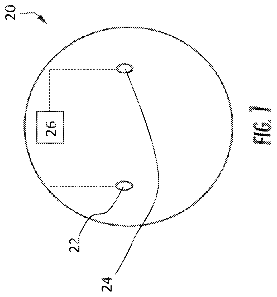
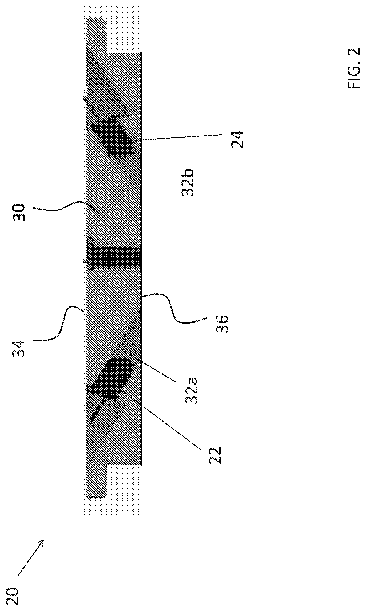
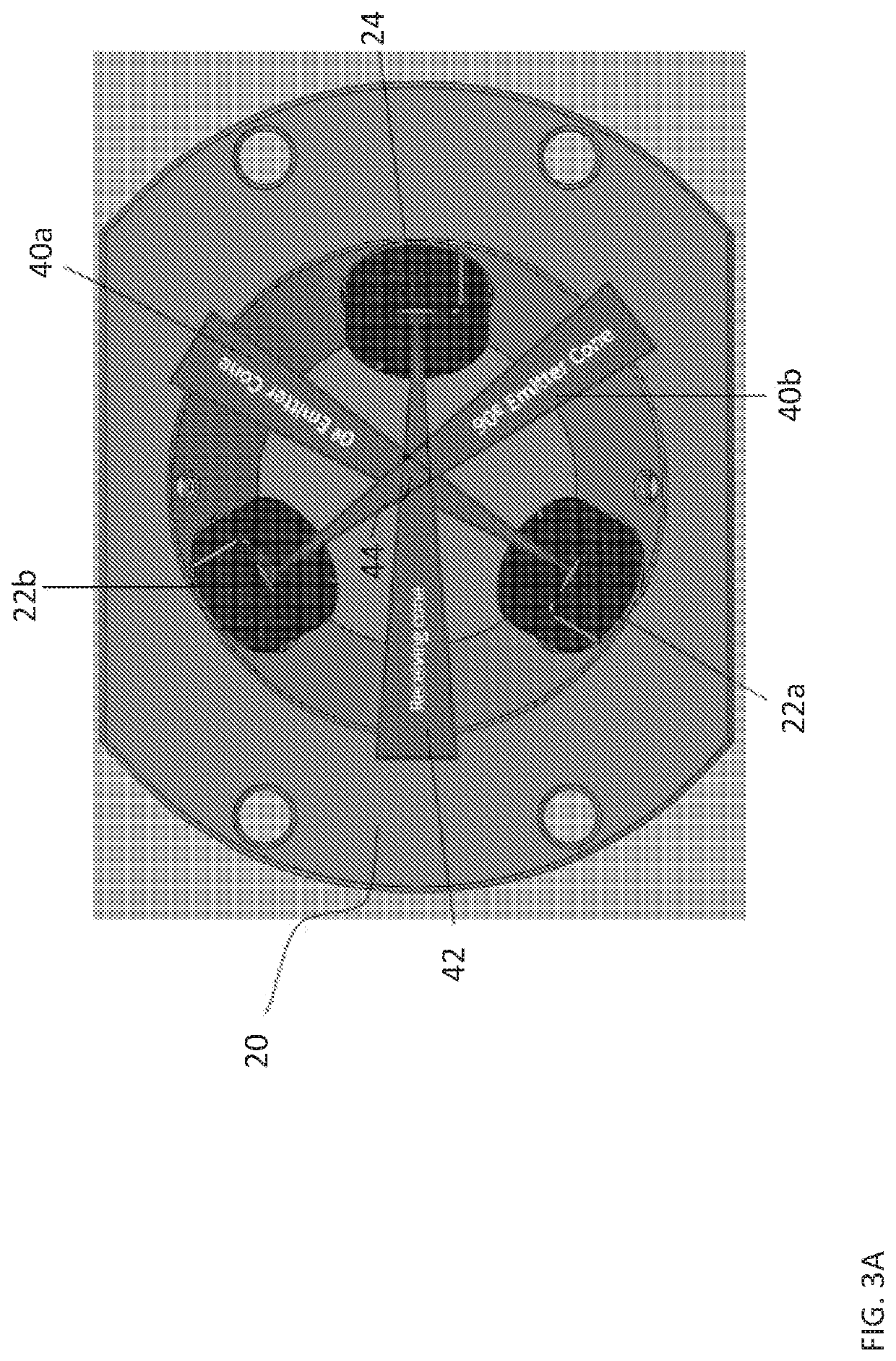
[0038]Referring now to the FIGS., an example of an optical detector 20 for detecting one or more conditions or events within a designated area to be monitored is illustrated. In the illustrated, non-limiting embodiment, the detection apparatus 20 is a chamber-less smoke detector. It will be appreciated that a chamber-less smoke detector may provide additional benefits including, but not limited to reduction of transport time for smoke to reach the sensor elements to enable faster response / alarm times, improved sensitivity, manufacturability, and reproducibility, negligible directionality, ease of maintenance, and enhanced aesthetics for example. However, it should be understood that in other embodiments, the detector 20 may be able to detect one or more hazardous conditions, including but not lim...


PUM


Abstract

A method of calibrating an optical detector includes affixing a calibration material to a first surface of the optical detector and calibrating one or more parameters of the optical detector using the calibration material.

Description

CROSS REFERENCE TO RELATED APPLICATIONS[0001]This application claims the benefit of U.S. Application No. 62 / 778,113, filed on Dec. 11, 2018, which is incorporated herein by reference in its entirety.BACKGROUND[0002]Embodiments of the present disclosure described herein generally relate to smoke detectors and, more particularly, to systems and methods for verifying operational integrity of optical smoke detectors.[0003]Smoke detectors exist including a light source that produces and emits a light beam into an area being monitored. A photo detector is positioned to receive light that is scattered by smoke particles from the area being monitored. A processing circuit is associated with the light source and the photo detector to measure the amount of light received and evaluate whether one or more smoke particles are present.[0004]The various components of the smoke detector contribute to the sensitivity of the detector and as a result, at the time of manufacture, the smoke detector req...

Claims


Application Information

Patent Timeline
IPC IPC(8): G01N21/53G08B17/107
CPCG01N21/53G01N2201/127G08B17/107G01N21/274G08B29/145G08B29/22
Inventor GULER, URCANLINCOLN, DAVID L.PIECH, MARCIN
Owner CARRIER CORP
Learn More