Optical collimating method and device for optical instrument and external light source

A technology for optical instruments and interface devices, applied in the field of simplifying the alignment between optical instruments and external light sources, to achieve the effect of convenient adjustment and low cost

Inactive Publication Date: 2005-08-24
SHANGHAI INST OF OPTICS & FINE MECHANICS CHINESE ACAD OF SCI
View PDF0 Cites 2 Cited by
  • Summary
  • Abstract
  • Description
  • Claims
  • Application Information

AI Technical Summary

Problems solved by technology

[0007] In order to solve the problem of precise alignment of the optical path between the existing optical instrument and the external light source, the present invention proposes a method for adjusting the optical path on the basis of the principle of positioning a straight line at two points

Method used


Image

  • Optical collimating method and device for optical instrument and external light source
  • Optical collimating method and device for optical instrument and external light source
  • Optical collimating method and device for optical instrument and external light source

Examples


Embodiment Construction

[0021] The present invention will be further described below in conjunction with accompanying drawing:

[0022] An optical interface method between an optical instrument and an external light source, which adopts the following operation steps:

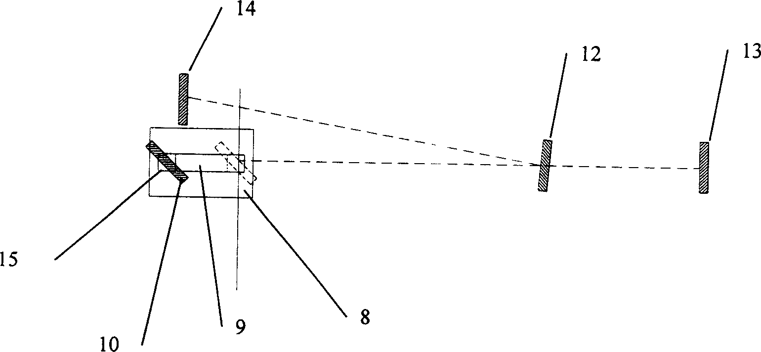
[0023] 1) platform 8, half mirror 12, receiving screen 13 and receiving screen 14 are fixed inside the optical instrument;

[0024] 2) When the optical instrument works normally, the reflector 10 remains at a position away from the incident light beam 1;

[0025] 3) Before moving the optical instrument or an external light source, first move the reflector 10 installed on the precision guide rail 9 and the slider 15 into the incident beam 1, and the reflector 10 reflects the incident beam 1 to a half-transparent mirror 12 On; the half mirror 12 transmits a part of the light to the receiving screen 13, and the other part is reflected on the receiving screen 14; at this time, the optical paths before and after the reflector 10 constitute...


PUM


Abstract

An optics interface method of optics instrument and external optical source and the device. Based on the theory of two points locating one straight line, promote a simplifying method of aligning method of the optics instrument and the external optical source. It requires that the optical path and the retardation between the external optical source and the two locating points are as long as possible, and the place of the receiving screen does not change, that is, the minor change of the emitting direction of the external optical source can bring about apparent movement of the facula of receiving screen, so as to improve the direction adjusting precision of the external optical source. The invention uses lens moving along the precision guide way to reduce the space of the device, and is convenient for the switch between the working state of the optics instrument and the state of the aligning adjustment of the external optical source. The strong point of this invention is that it can accurately align the external optical source to the internal optical path of the optics instrument, and the adjustment is convenient and the cost is low.

Description

Technical field: [0001] The invention relates to a method for adjusting an optical path, in particular to a method for simplifying the alignment of an optical instrument and an external light source. Background technique: [0002] Many optical instruments that require an external light source have complex internal optical paths. After the optical instrument or external light source is moved, the internal optical path needs to be readjusted. The adjustment process is complicated and cumbersome. Therefore, it is hoped that there is a method that can easily restore the orientation of the external light source so that it can be aligned with the internal optical path of the optical instrument. This is the problem of the optical interface between the optical instrument and the external light source. [0003] Usually, the principle of two points positioning a straight line is used to realize the alignment of the optical path. A commonly used optical interface solution is to use th...

Claims


Application Information

Patent Timeline
IPC IPC(8): G02B27/62
Inventor 范树海贺洪波赵元安邵建达范正修
Owner SHANGHAI INST OF OPTICS & FINE MECHANICS CHINESE ACAD OF SCI
Why Eureka
Try Eureka