Spinal plate selection and positioning system
Pending Publication Date: 2021-12-02
RETROSPINE
View PDF0 Cites 0 Cited by
- Summary
- Abstract
- Description
- Claims
- Application Information
AI Technical Summary
Benefits of technology
The present patent application is a continuation of several related patent applications filed between July 2012 and July 2018. The technical effects of the patent application include the development of a system for properly aligning and positioning interbody plates and interbody cages in spinal-fusion surgery procedures. The system addresses the difficulty of accurately positioning these components due to narrow wounds, blood or tissue obfuscation, and the lack of control over the positioning of the interbody cage relative to the interbody plate. The system utilizes a trial cage connected to a drill guide for temporary installation and the removal of the trial cage and drill guide to implant the interbody cage, followed by the positioning and fastening of the interbody plate to the vertebrae. The system provides a more reliable and controlled method for aligning and positioning these components.
Problems solved by technology
In practice, however, proper alignment and positioning of the interbody cage may be difficult to accomplish due to (i) narrow wounds which obscure surgical landmarks; (ii) blood or other tissue may obscure landmarks; (iii) the interbody plate itself may obscure landmarks; (iv) drill guides that are used to drill pilot holes may further obscure landmarks; and (v) the interbody plate may move prior to being secured without the surgeon being aware.
This technique, however, has limitations.
One limitation is that there is no assurance that the trial cage and the actual interbody cage are located in the same position.
Another limitation is that there is no assurance that the interbody plate is positioned correctly with respect to the pilot holes.
A further limitation is that the positioning of the interbody cage relative to the interbody plate is not controlled.
For example, many of the prior art devices cannot assure that an interbody plate and interbody cage are ideally positioned.
Method used
View moreImage
Smart ImageViewing Examples
Examples
embodiment 2
f embodiment 1, wherein said aligning and positioning the interbody plate, further including:
[0173]inserting a portion of the elongated guide member, into the interbody cage.
embodiment 3
f embodiment 2, wherein the elongated guide member includes a drill guide having a plurality of guide tubes that extend through the drill guide.
embodiment 4
f embodiment 3, wherein the plurality of guide tubes extend through the drill guide at fixed angles.
Login to View More PUM
 Abstract
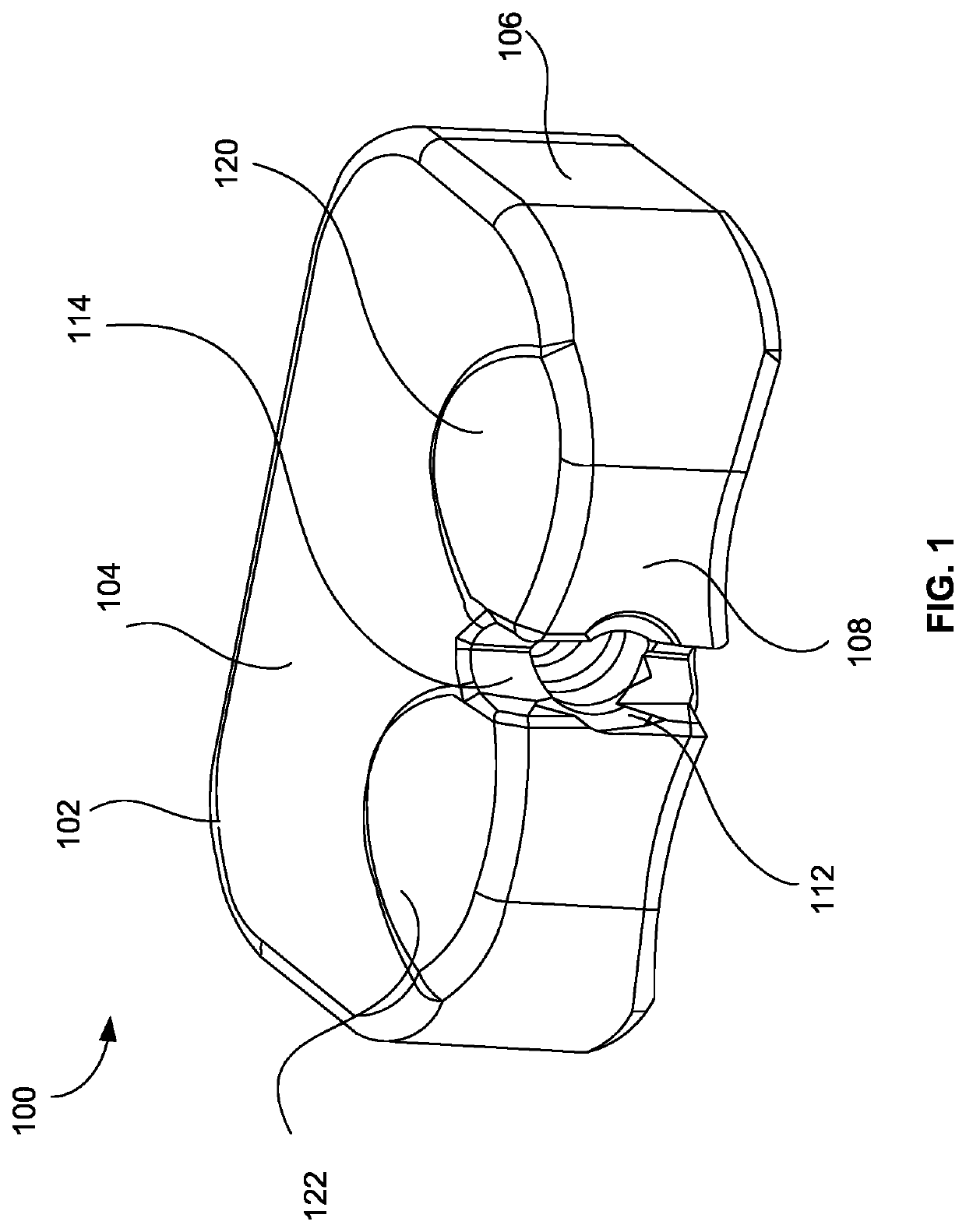
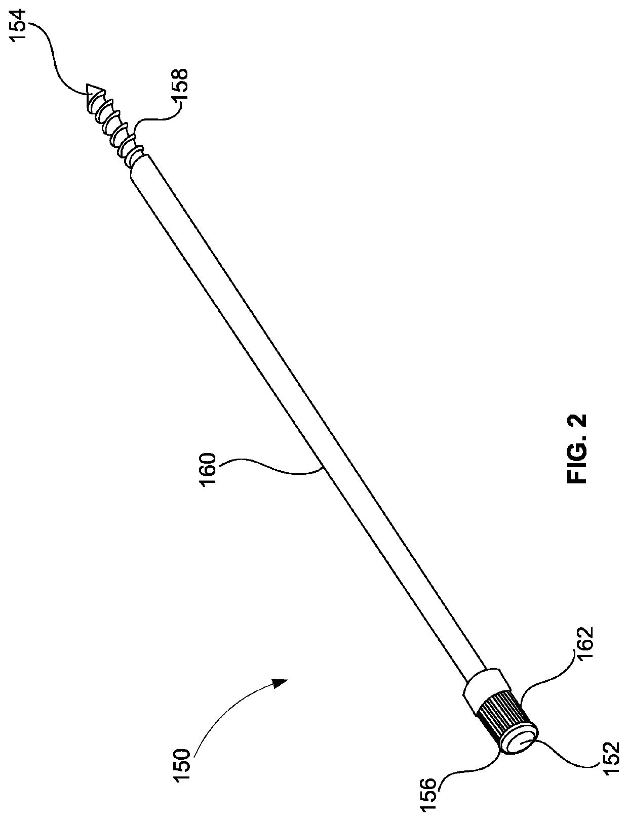
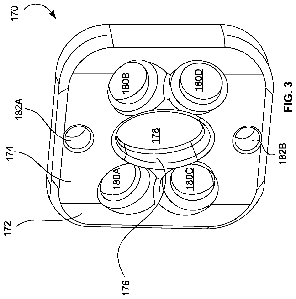
A spinal plate selection and positioning system is provided for use in a spinal fusion procedure. The system may comprise an elongated guide member that is removably securable to an interbody cage by a holding rod. An interbody plate may be aligned and positioned above the interbody cage installed in a disc space. A drill guide may also be aligned and positioned above the interbody plate. The drill guide may be utilized to drill pilot holes in the vertebrae defining the disc space. Fasteners to secure the interbody plate may also by installed using the drill guide. The use of the guide member ensures that the interbody plate is properly aligned and positioned with respect to the interbody cage.
Description
CROSS-REFERENCE TO RELATED APPLICATIONS[0001]This application is a continuation of U.S. patent application Ser. No. 17 / 114,299, filed Dec. 7, 2020, which is a continuation of U.S. patent application Ser. No. 16 / 937,456, filed Jul. 23, 2020, which is a continuation of U.S. patent application Ser. No. 16 / 812,146, filed Mar. 6, 2020, which is a continuation of U.S. patent application Ser. No. 16 / 598,999, filed Oct. 10, 2019, which is a continuation of U.S. patent application Ser. No. 16 / 428,564, filed May 31, 2019, which is a continuation of U.S. patent application Ser. No. 16 / 237,565, filed Dec. 31, 2018, which is a continuation of U.S. patent application Ser. No. 16 / 049,623, filed Jul. 30, 2018, which is a continuation of U.S. patent application Ser. No. 15 / 908,610, filed Feb. 28, 2018, which is a continuation of International Application Serial No. PCT / IB2016 / 002025, with an international filing date of Aug. 29, 2016, which claims the benefit of U.S. Provisional Application No. 62 / 2...
Claims
Login to View More Application Information
Patent Timeline
 IPC IPC(8): A61F2/44A61B17/16A61B17/17A61F2/46
CPCA61F2/4455A61B17/1633A61F2/4611A61F2/442A61B17/1757A61B17/1728A61F2/447A61F2002/30593A61F2002/30836A61F2002/4627A61F2002/4629
Inventor SEEX, KEVIN
Owner RETROSPINE
Features
- R&D
- Intellectual Property
- Life Sciences
- Materials
- Tech Scout
- Unparalleled Data Quality
- Higher Quality Content
- 60% Fewer Hallucinations
Learn More Browse by: Latest US Patents, China's latest patents, Technical Efficacy Thesaurus, Application Domain, Technology Topic, Popular Technical Reports.
© 2025 PatSnap. All rights reserved.Legal|Privacy policy|Modern Slavery Act Transparency Statement|Sitemap|About US| Contact US: help@patsnap.com


