
Passive pump

a pump and bypass technology, applied in the field of bypass pump, can solve the problems of heart failure, heart failure, heart failure, etc., and achieve the effect of facilitating fluid movement and cyclical movemen

Active Publication Date: 2021-11-25
GROSS YOSSI
View PDF2 Cites 1 Cited by
  • Summary
  • Abstract
  • Description
  • Claims
  • Application Information

AI Technical Summary

Benefits of technology

The present invention describes an apparatus that can be implanted in a patient's heart to facilitate the cyclical movement of fluid (not blood) into and out of the ventricle during the cardiac cycle. This movement helps to reduce the volume of blood in the ventricle during relaxation and contraction stages, which can help to reverse remodeling of the ventricle and restore it to a healthy geometry. The apparatus uses a passive pump that is responsive to changes in pressure to move the fluid between components of the pump. The invention can be used to acutely reduce the ejection fraction of the heart by reducing the volume of blood in the ventricle. This may help to further reduce wall stress and promote reverse remodeling of the ventricle.

Problems solved by technology

In some cases, the heart cannot fill with enough blood.
In other cases, the heart cannot pump blood to the rest of the body with enough force.
Heart failure develops over time as the heart's pumping action grows weaker.
Systolic heart failure occurs when the contraction of the muscle wall of the left ventricle malfunctions, which compromises its pumping action.
In general, left-sided heart failure leaves the heart unable to pump enough blood into the circulation to meet the body's demands, and increasing pressure within the heart causes blood to back up in the pulmonary circulation, producing congestion.

Method used


Image

  • Passive pump
  • Passive pump
  • Passive pump

Examples


Embodiment Construction

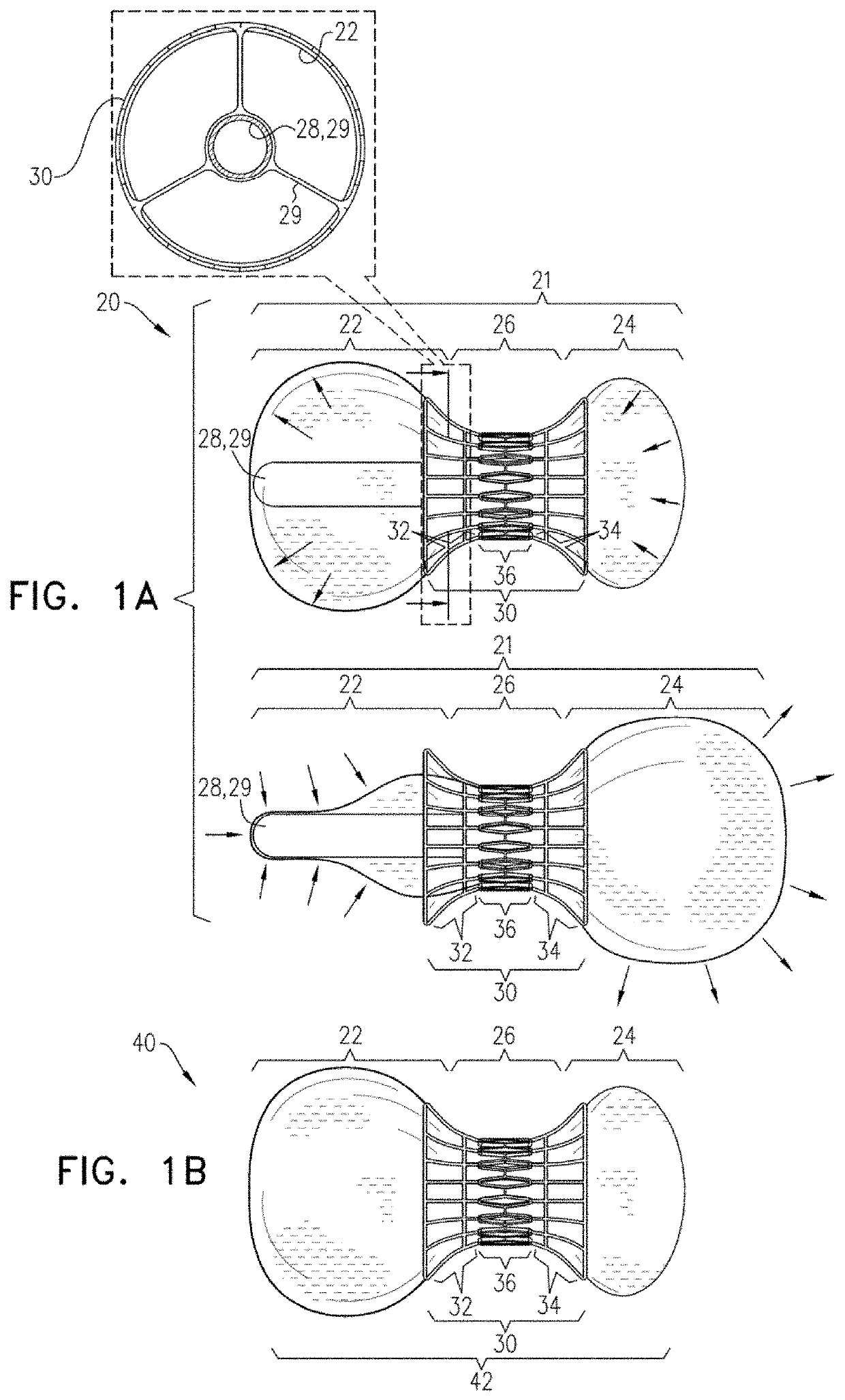
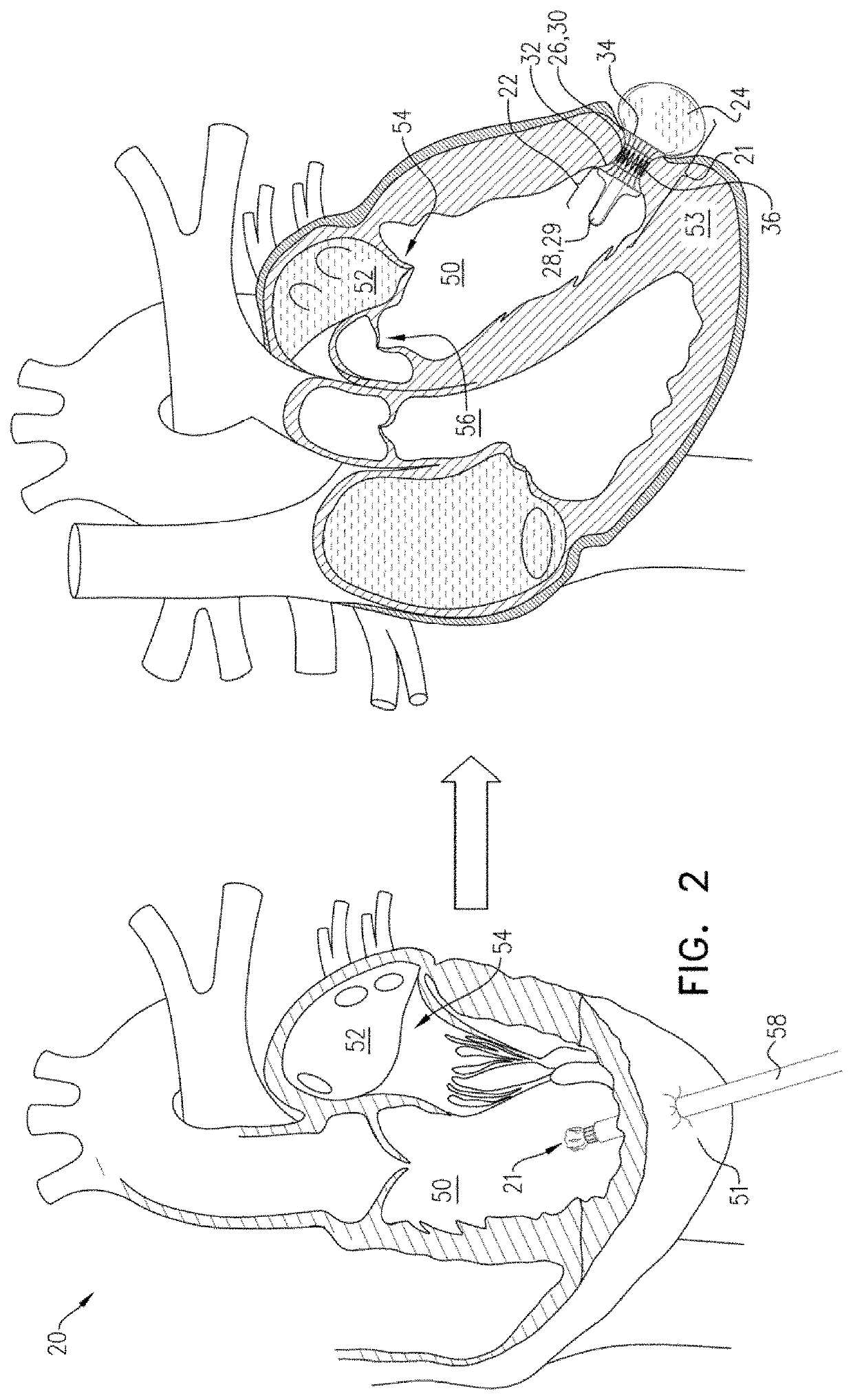
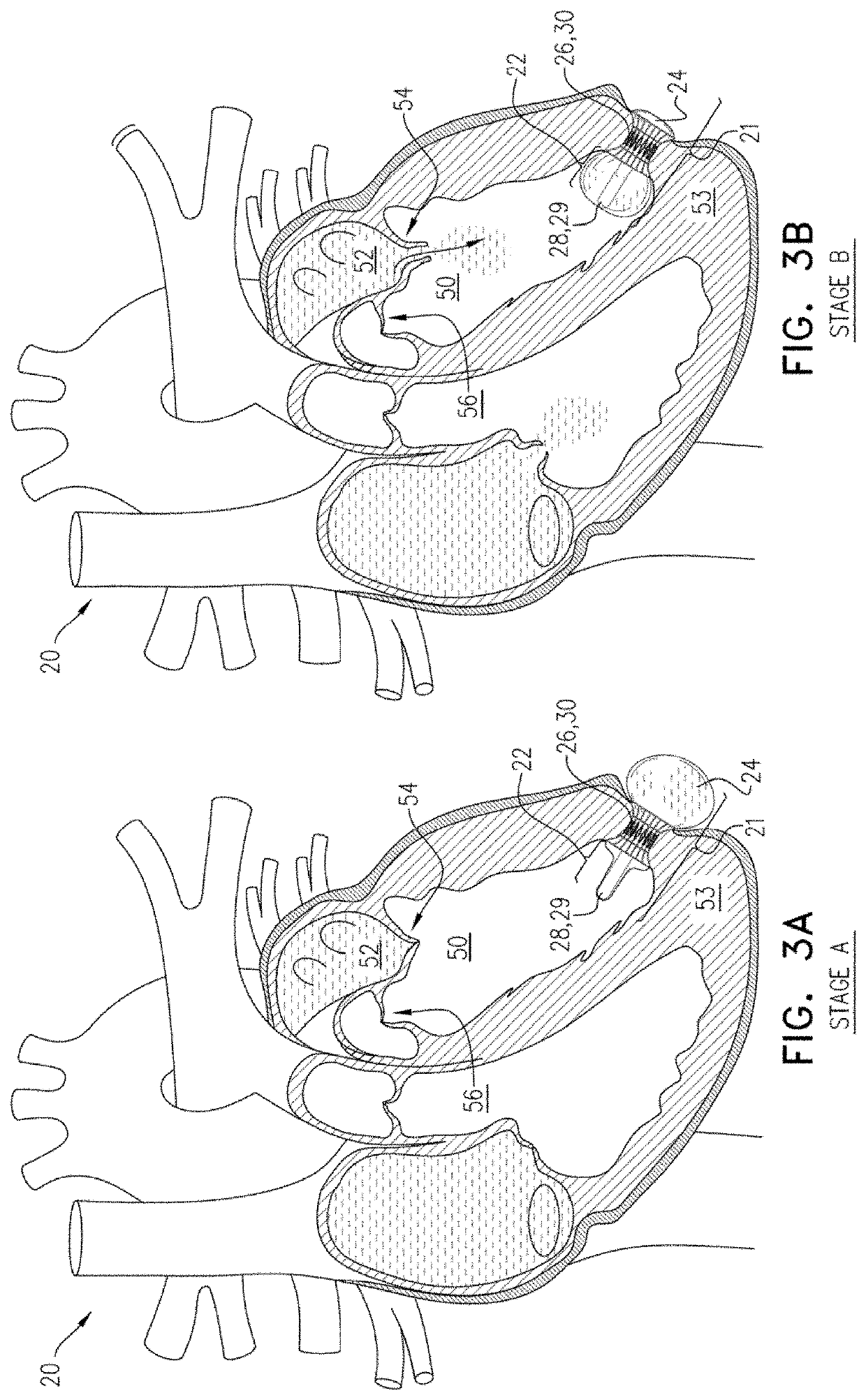
[0080]Reference is now made to FIG. 1A, which is a schematic illustration of a system 20 comprising a passive pump 21 which comprises a noncompliant bag 22 and a compliant balloon 24, in accordance with some applications of the present invention. A conduit 26 is disposed between and in fluid communication with bag 22 and compliant balloon 24. Passive pump 21 defines a total internal space disposed within conduit 26, bag 22, and compliant balloon 24. Fluid is disposed within the internal space and is passable between bag 22 and compliant balloon 24 via conduit 26. Typically, the internal space contains 10-80 ml of fluid, e.g., 20-40 ml of fluid. Typically, the fluid comprises fluid that is not blood of the patient. For some applications of the present invention, the fluid comprises a gas, such as carbon dioxide, or a liquid, such as saline. Alternatively or additionally, the fluid comprises a reduced-osmolarity fluid, e.g., a contrast-agent fluid which is used for imaging and is know...


PUM


Abstract

Apparatus is provided, including a flexible intraventricular receptacle positionable within a heart ventricle, and configured to assume a first volume upon passage of fluid that is not blood into the receptacle and a second, smaller volume upon passage of the fluid out of the receptacle. An expandable extracardiac receptacle is positionable outside of the heart, and is configured to expand upon transfer of the fluid into the extracardiac receptacle from the intraventricular receptacle and to contract upon passage the fluid out of the extracardiac receptacle. A transmyocardial conduit is disposed and allows passage of the fluid between the intraventricular receptacle and the extracardiac receptacle responsively to a cardiac cycle. During ventricular systole, a volume of fluid is expelled from the intraventricular receptacle, through the conduit, and the extracardiac receptacle, producing a corresponding decrease in a total volume of the ventricle during isovolumetric contraction of the ventricle.

Description

FIELD OF THE INVENTION[0001]The present invention relates in general to heart repair. More specifically, the present invention relates to a method of repairing a failing heart utilizing a passive device which assists a ventricle of the heart.BACKGROUND OF THE INVENTION[0002]Heart failure is a condition in which the heart cannot pump enough blood to meet the body's needs. In some cases, the heart cannot fill with enough blood. In other cases, the heart cannot pump blood to the rest of the body with enough force.[0003]Heart failure develops over time as the heart's pumping action grows weaker. The condition can affect one or both sides of the heart.[0004]Systolic heart failure occurs when the contraction of the muscle wall of the left ventricle malfunctions, which compromises its pumping action. This causes a decrease in the ejection fraction below the normal range, and gradually, left ventricular remodeling occurs in the cardiac tissue which causes enlargement of the ventricle. The r...

Claims


Application Information

Patent Timeline
Patent Type & Authority Applications(United States)
IPC IPC(8): A61M1/10A61M1/12
CPCA61M1/1074A61M1/1044A61M1/122
Inventor GROSS
Owner GROSS YOSSI
Learn More