Measuring apparatus and method for capsules

a technology of measuring apparatus and capsules, which is applied in the direction of apparatus for force/torque/work measurement, instruments, transportation and packaging, etc., can solve the problems of capsule tilt, force measurement detected by known-type apparatuses for measuring the pull-off force of connecting elements of capsules turns out to be poorly reliable, etc., and achieves the effect of convenient installation

Active Publication Date: 2021-11-18
SACMI COOP MECCANICI IMOLA S C R L
View PDF2 Cites 0 Cited by
  • Summary
  • Abstract
  • Description
  • Claims
  • Application Information

AI Technical Summary

Benefits of technology

[0024]Moreover, the measuring apparatus according to the invention may be easily installed in pre-existing capsule processing lines without needing to make substantial changes to the processing line itself.
[0025]Moreover, in an example of measuring apparatus according to the invention, it is possible to provide a measuring apparatus for measuring the pull-off force of the connecting elements of a capsule, which allows for a rotation of the capsule around its longitudinal axis, such that a vision system may detect features of the tamper evident band and / or of the connecting elements, such as a size of the bridge elements, an angular distribution of the bridge elements, a regularity of the cut made by a knife, intended for forming the tamper evident band, or safety ring, of the capsule.

Problems solved by technology

However, known-type apparatuses for measuring the pull-off force of connecting elements of a capsule have some limits and drawbacks.
Moreover, the force measurements detected by the known-type apparatuses for measuring the pull-off force of connecting elements of a capsule turn out to be poorly reliable, as some bridge elements may not be subjected to a tensile force since no strain is applied thereto.
This implies the risk that the capsule might tilt with respect to the longitudinal axis of the capsule, along which the force applied by the piston is directed, and that the piston might continue its stroke without abutting against the capsule due to the tilting thereof.
As a result, some bridge elements may undergo no stress, the measurement of the detected pull-off force thus turning out to be inaccurate.

Method used


Image

  • Measuring apparatus and method for capsules
  • Measuring apparatus and method for capsules
  • Measuring apparatus and method for capsules

Examples


Embodiment Construction

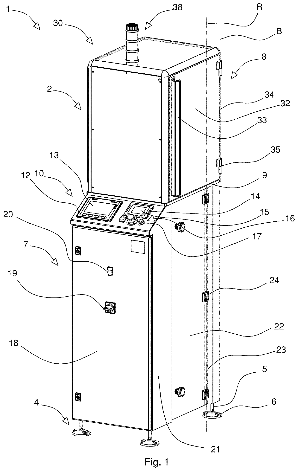
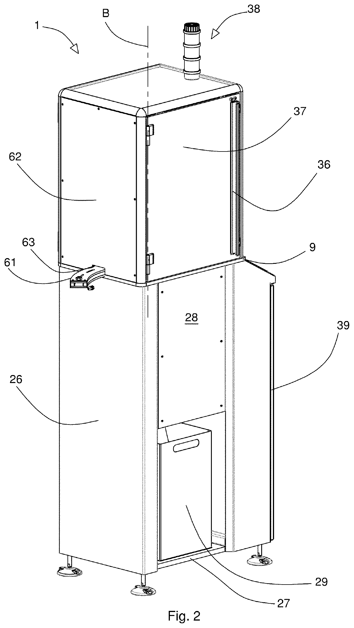
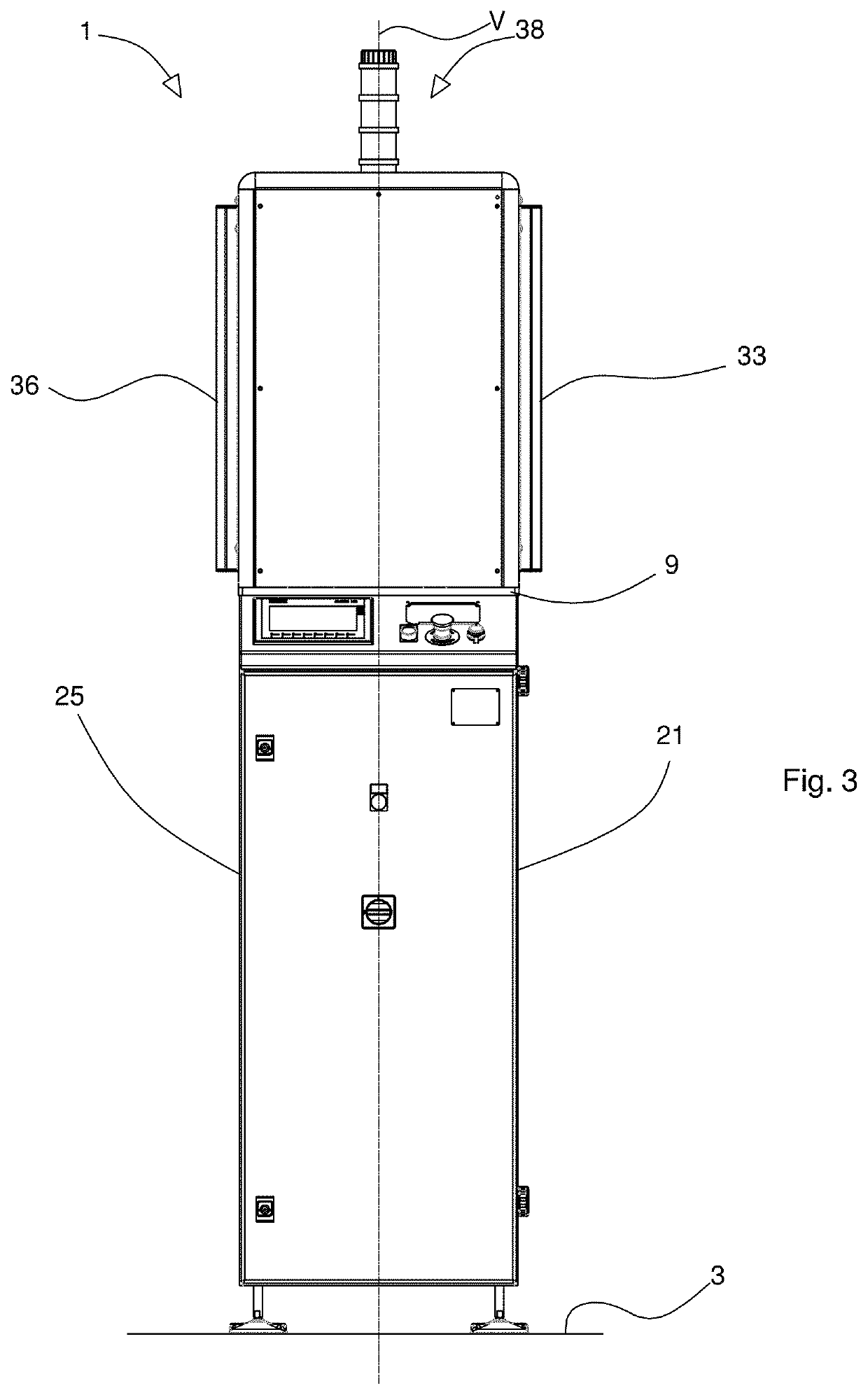
[0082]Referring to the aforementioned figures, a measuring apparatus, also called PFM, which stands for Pull Force Machine, is indicated as a whole by reference numeral 1, and is arranged to measure the pull-off force of connecting elements 201 (FIGS. 6 and 8) with which a capsule, or closure, 200 (FIG. 6) is provided. Specifically, the measuring apparatus 1 measures the pull-off force of the connecting elements 201 by subjecting the capsule 200, and hence the connecting elements 201, to a tensile force.

[0083]The capsule 200 is made of plastic material, and is of the kind used for closing containers such as bottles, for example.

[0084]The connecting elements 201 are arranged to connect portions of a side wall 202, with which the capsule 200 is provided, and which may be cylindrical in shape, to portions of a tamper evident band, or safety ring, 203, with which the capsule 200 is provided, and which are substantially annular in shape. The tamper evident band 203 is suitable to provide...


PUM

PropertyMeasurementUnit
angleaaaaaaaaaa
lengthaaaaaaaaaa
heightaaaaaaaaaa

Abstract

There are disclosed a measuring apparatus and method for measuring the pull-off force of a frangible arrangement connecting a capsule with a tamper evident band of closed annular shape, with an annular ridge that axially retains the tamper evident band, a pusher device that pushes the capsule so as to cause the breakage of the frangible arrangement, a sensor arrangement to detect the tensile force applied by the pusher device, and a lifting and abutting device arranged for supply the capsule to the annular ridge.
There are further disclosed a band disengagement arrangement for disengaging the tamper evident band from the annular ridge after the breakage of the frangible arrangement, yet maintaining intact the closed annular shape of the tamper evident band.

Description

CROSS-REFERENCE TO RELATED APPLICATIONS[0001]This application claims priority of Italian Patent Application Nos. IT02020000011038 filed on May 14, 2020 and IT102020000032168 filed on Dec. 23, 2020. The entire content of these applications is incorporated herein by reference.BACKGROUND OF THE INVENTION[0002]The invention relates to a measuring apparatus and method for measuring the pull-off force of connecting elements of a capsule or a closure, specifically of capsules or closures made of plastic material of the kind used for closing containers such as bottles, for example.[0003]Specifically, but not exclusively, this invention relates to a measuring apparatus and method for measuring the pull-off force of connecting elements arranged for connecting portions of a side wall of the capsule to portions of a tamper evident band, or safety ring, with which the capsule is provided. Specifically, the connecting elements comprise bridge elements, or bridges, namely elements made of plastic ...

Claims


Application Information

Patent Timeline
Patent Type & Authority Applications(United States)
IPC IPC(8): G01N3/08G01N3/06
CPCG01N3/08G01N3/066G01N2203/04G01N2203/0067G01N2203/0017G01L5/00G01N2203/0676G01M99/007G01L5/0071B65D55/16B65D41/3447
Inventor ALBONETTI, DANILO
Owner SACMI COOP MECCANICI IMOLA S C R L
Why Eureka
Try Eureka