Pneumatic tire

a pneumatic tire and rubber technology, applied in the field of pneumatic tires, can solve the problems of insufficient braking performance on wet road surfaces and snow-covered road surfaces based on sipes, poor appearance of vulcanized pneumatic tires, and tire appearance changes, so as to achieve effective enhancement of bonding between tire mold and tread rubber, and effective suppression of poor appearance

Pending Publication Date: 2021-10-21
THE YOKOHAMA RUBBER CO LTD
View PDF1 Cites 0 Cited by
  • Summary
  • Abstract
  • Description
  • Claims
  • Application Information

AI Technical Summary

Benefits of technology

[0004]The present technology provides a pneumatic tire that allows enhancing braking performance on wet road surfaces and snow-covered road surfaces without changing an appearance of the tire, and reducing poor appearance.
[0007]In the embodiment of the present technology, the boundary region is preferably a region within 15 mm on one side in the tire circumferential direction with the dividing position of each of the plurality of sectors as a center. As a result, poor appearance can be effectively suppressed while the braking performance on wet road surfaces and snow-covered road surfaces is effectively enhanced.
[0008]In the embodiment of the present technology, the at least one shallow bottom sipe preferably has a depth in a range of from 30% to 80% to an average maximum depth of the plurality of regular sipes in each of the plurality of rows of land portions including the at least one shallow bottom sipe. As a result, the bonding between the tire mold and the tread rubber can be effectively suppressed while the braking performance on wet road surfaces and snow-covered road surfaces is effectively enhanced.
[0009]In the embodiment of the present technology, the shallow bottom sipes are preferably disposed most in each of the plurality of rows of land portions located on an outer side in the tire width direction among the plurality of rows of land portions in the tread portion. As a result, a mold release property of the sipes can be enhanced, and the bonding between the tire mold and the tread rubber can be effectively suppressed.
[0010]In the embodiment of the present technology, an inclination angle of each of the plurality of sipes with respect to the dividing line of each of the plurality of sectors is defined as θ, the number of the shallow bottom sipes that satisfy 0°≤θ≤30° is preferably larger than the number of the shallow bottom sipes that do not satisfy 0°≤θ≤30°. As a result, the bonding between the tire mold and the tread rubber can be effectively suppressed.

Problems solved by technology

When a pneumatic tire having a plurality of sipes in a tread portion is vulcanized and molded, there is a problem that a tire mold and a tread rubber are bonded and poor appearance occurs in the vulcanized pneumatic tire.
However, reducing the number of sipes and shortening the length in the tire width direction not only changes the appearance of the tire, but also causes a problem that braking performance on wet road surfaces and snow-covered road surfaces based on the sipes cannot be sufficiently obtained.

Method used


Image

  • Pneumatic tire
  • Pneumatic tire
  • Pneumatic tire

Examples


example

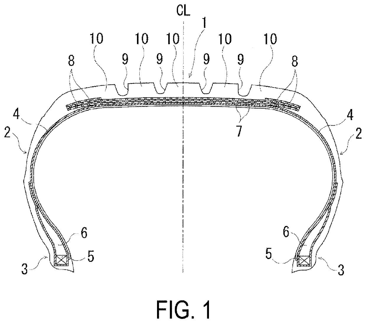
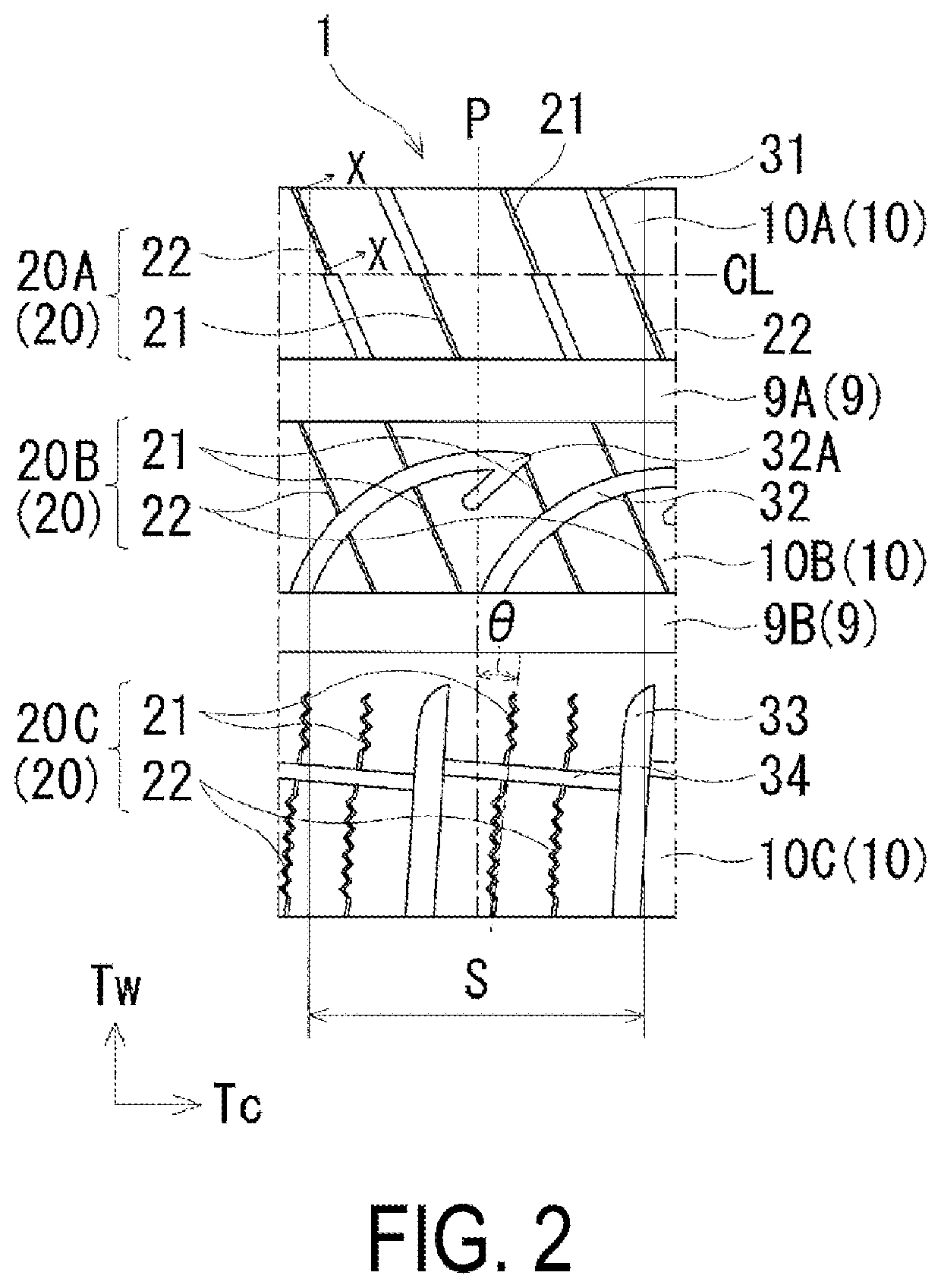
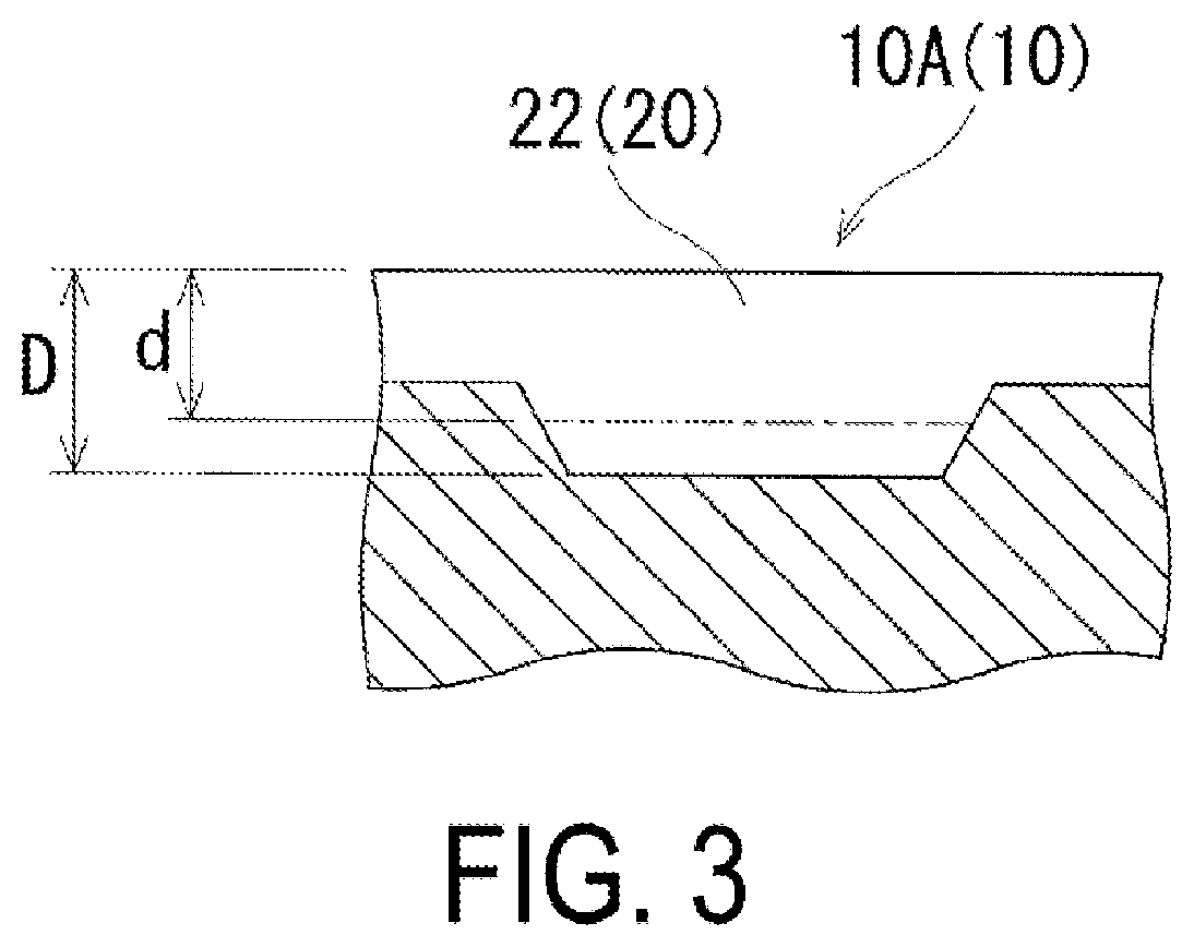
[0034]In a pneumatic tire having a tire size of 205 / 55R16 that includes a plurality of circumferential grooves extending in a tire circumferential direction in a tread portion, a plurality of rows of land portions defined by the circumferential grooves, a plurality of sipes extending in a tire width direction in at least one row of the land portion, and the tread portion molded by a plurality of sectors divided in the tire circumferential direction, the presence of the sipe in a boundary region, the presence of a shallow bottom sipe, the range of the boundary region, the proportion of raised bottom of the shallow bottom sipe, the comparison of the number of the shallow bottom sipes in each land portion, the inclination angle θ of the sipe in the center land portion, the inclination angle θ of the sipe in the intermediate land portion, and the inclination angle θ of the sipe in the shoulder land portion were set as in Table 1, and tires of Conventional Example, Comparative Example, a...


PUM


Abstract

A pneumatic tire includes a tread portion molded by sectors divided in a tire circumferential direction. The pneumatic tire includes circumferential grooves, rows of land portions, and sipes. The circumferential grooves extend in the tire circumferential direction in the tread portion. The rows of land portions are defined by the circumferential grooves. The sipes extend in a tire width direction in at least one row of the rows of land portions. The sipes include at least one shallow bottom sipe and regular sipes. The at least one shallow bottom sipe is disposed in a boundary region including a dividing position of each of the sectors. The regular sipes are disposed at positions more separated from the dividing position of each of the sectors than the at least one shallow bottom sipe. The at least one shallow bottom sipe is shallower than the regular sipes.

Description

TECHNICAL FIELD[0001]The present technology relates to a pneumatic tire and particularly relates to a pneumatic tire that allows enhancing braking performance on wet road surfaces and snow-covered road surfaces without changing an appearance of the tire, and reducing poor appearance.BACKGROUND ART[0002]When a pneumatic tire having a plurality of sipes in a tread portion is vulcanized and molded, there is a problem that a tire mold and a tread rubber are bonded and poor appearance occurs in the vulcanized pneumatic tire. Such a bonding between the tire mold and the tread rubber is significant in winter tires in which a large number of sipes are disposed in a tread portion. In contrast, it has been proposed to reduce the number of sipes in a boundary region including a divided position of a sector and shorten a length of a sipe in a tire width direction (for example, see Japan Patent Nos. 3494511 and 4411975).[0003]However, reducing the number of sipes and shortening the length in the...

Claims


Application Information

Patent Timeline
Patent Type & Authority Applications(United States)
IPC IPC(8): B60C11/12
CPCB60C11/1259B60C2011/1213B60C11/1236B60C11/1204B60C11/0306B60C2011/0381B60C2011/1209B60C11/1263B60C2011/1268B60C2011/036B60C2011/0365B60C2011/0372B60C2011/0341B60C11/04B60C2200/04B60C2011/1227B60C11/12
Inventor NAGAYASU, MASAAKI
Owner THE YOKOHAMA RUBBER CO LTD
Why Eureka
Try Eureka