LOCALIZED STRAIN FIELDS IN EPITAXIAL LAYER OVER cREO

a technology of epitaxial layer and creo, which is applied in the direction of instruments, semiconductor devices, electrical apparatus, etc., can solve the problems of complex manufacturing, large etching and deposition of metals, etc., and achieve the effects of improving epitaxially grown devices, improving efficiency, and being more complicated to manufactur

Active Publication Date: 2021-10-14
IQE
View PDF2 Cites 0 Cited by
  • Summary
  • Abstract
  • Description
  • Claims
  • Application Information

AI Technical Summary

Benefits of technology

[0004]In some cases, acoustic Bragg reflectors (ABR) are used to surround a resonant cavity to form resonators. Such resonators can improve efficiency but are much more complicated to manufacture. In the present invention, a second layer sandwiched between a substrate layer and an epitaxial layer can locally stress the epitaxial layer. By providing a layer that can locally stress the subsequent-grown layer, improved epitaxially-grown devices can be made. The second layer can include a plurality of discrete regions formed over the substrate layer. Each of the discrete regions is adjacent to another discrete region. Each discrete region includes at least two different materials, for example, each discrete region can include two of the following material, cREO, non-porous silicon, porous silicon, and fully-depleted porous silicon. These discrete regions produce a localized stress that may be used to manipulate in-plane characteristics of the epitaxial layer that is formed over the second layer that has the discrete regions.
[0005]For example, a discrete region can include a first subregion and a second subregion. The discrete regions can include a crystalline rare earth oxide and a second material (e.g., non-porous silicon, porous silicon, silicon oxide (SiO2), etc.). Such discrete regions in the second layer can improve epitaxial growth of additional materials over the patterned template wafer.

Problems solved by technology

With complex epitaxial structures often incorporating more than one device functionality, this can require extensive etching and deposition of metals on wafers with a large amount of topography.
Such resonators can improve efficiency but are much more complicated to manufacture.

Method used


Image

  • LOCALIZED STRAIN FIELDS IN EPITAXIAL LAYER OVER cREO
  • LOCALIZED STRAIN FIELDS IN EPITAXIAL LAYER OVER cREO
  • LOCALIZED STRAIN FIELDS IN EPITAXIAL LAYER OVER cREO

Examples


Embodiment Construction

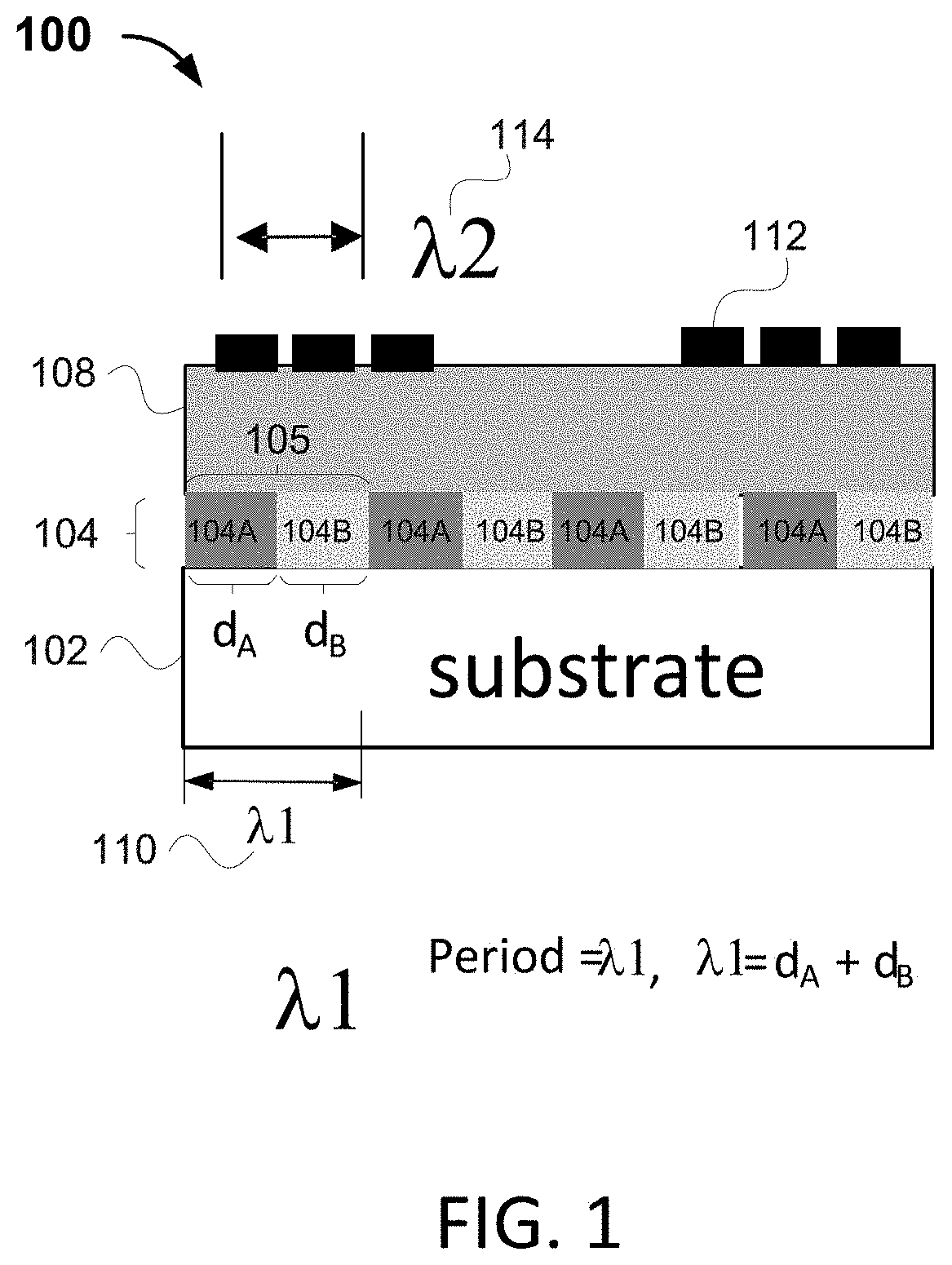
[0036]Structures and methods described herein provide a layered structure including a substrate layer, a second layer over the substrate and an epitaxial layer over the second layer. The second layer is integrated between the substrate layer and the epitaxial layer, and incorporates discrete regions to impart localized stress within an epitaxial layer that transmits an acoustic wave.

[0037]FIG. 1 shows a cross-sectional view of an illustrative layered structure with a second layer between a substrate and a semiconductor layer, matched to a periodicity of an acoustic wavelength, according to an illustrative embodiment. Layered structure 100 may be used as an RF filter. Layered structure 100 includes a substrate 102, a second layer 104 over the substrate layer 102, an epitaxial layer 108 grown over the second layer, and electrodes 112 disposed over the top of the epitaxial layer. The second layer 104 includes discrete regions 105. Each discrete region 105 includes a first subregion 104...


PUM


Abstract

A layered structure (100) for transmission of an acoustic wave, the layered structure (100) comprising: a substrate layer (102); and a second layer (104) over the substrate layer (102), wherein the second layer (104) comprises a plurality of discrete portions (105) adjacent to each other, each discrete portion (105) of the plurality of discrete portions (105) comprising a first subregion (104A) and a second subregion (104B). Also an epitaxial layer (108), grown over the second layer (104), for transmission of the acoustic wave in a major plane of the epitaxial layer (108), wherein a periodicity (λ) of a wavelength of the acoustic wave to be transmitted through the epitaxial layer (108) is approximately equal to a sum of a width (dA) of the first subregion (104A) and a width (dB) of the second subregion (104B).

Description

INTRODUCTION[0001]This application relates to semiconductor designs, and more specifically, to a layered structure for transmission of an acoustic wave through a locally stressed epitaxial layer, in which a second layer, sandwiched between the substrate and the epitaxial layer includes discrete regions that locally stress the epitaxial layer and improve the transmission of the acoustic wave through the epitaxial layer.BACKGROUND[0002]Epitaxy, epitaxial growth, and epitaxial deposition refer to growth or deposition of a crystalline layer on a crystalline substrate. The crystalline layer is referred to as an epitaxial layer. The crystalline substrate acts as a template and determines the orientation and lattice spacing of any epitaxial layer. The epitaxial layer can be, in some examples, lattice-matched or lattice-coincident. A lattice matched crystalline layer can have the same or a very similar lattice spacing as the top surface of the crystalline substrate. A lattice-coincident cry...

Claims


Application Information

Patent Timeline
Patent Type & Authority Applications(United States)
IPC IPC(8): H01L29/84H01L21/62H01L21/02
CPCH01L29/84H01L21/02565H01L21/02532H01L21/62G10K11/36G10K11/04G10K11/28H10N30/875H10N30/20H10N30/05H03H9/02574H03H9/02566H03H9/02866H03H9/02637H03H3/08H03H9/14511H03H9/02653H10N30/079
Inventor CLARK, ANDREWPELZEL, RODNEYHAMMOND, RICHARD
Owner IQE
Why Eureka
Try Eureka