Cooling system with thermal storage

Active Publication Date: 2021-10-14
ROCKY RES
View PDF0 Cites 1 Cited by
  • Summary
  • Abstract
  • Description
  • Claims
  • Application Information

AI Technical Summary

Benefits of technology

This patent describes a system for cooling high-energy lasers using a thermal energy storage system. The system includes a phase change material that can quickly transition from solid to liquid and vice versa, a cooling loop with a heat transfer fluid, and a control system to activate the cooling system when needed. The cooling system can discharge the thermal energy storage system in less than five minutes, providing a more efficient way to cool high-energy lasers.

Problems solved by technology

However, these systems alone do not generally provide the rapid cooling features necessary to cool a system that outputs bursts of heat.
A vapor compression system may take up to a minute, or in some cases more time, to reach full capacity and usually several minutes or longer to provide cooling to the target heat load.
These chilled water systems are reliable but also heavy and bulky as they rely only on the heat capacity of water.
Ice storage systems are more compact and lighter than chilled water due to the phase change energy of ice to water, but heat transfer problems for rapid melting and freezing of ice as required for burst cooling, along with the requirement to recharge at temperatures below 0° C. even if the cooling temperature is around 20° C., proved disadvantageous.
Paraffins have been used as phase change material in prior systems, although they were not found to be advantageous for cooling rapid bursts of heat.
Unfortunately, several properties of paraffin wax, such as its heat transfer properties and melting dynamics resulted in it being a poor choice for applications designed to rapidly cool systems which output bursts of heat.

Method used


Image

  • Cooling system with thermal storage
  • Cooling system with thermal storage
  • Cooling system with thermal storage

Examples


example

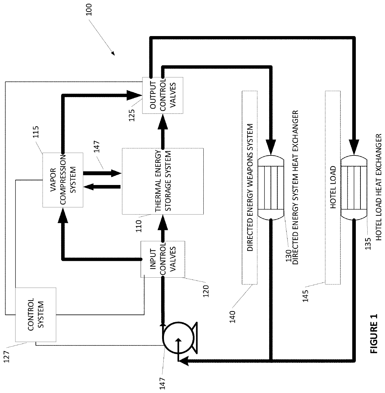
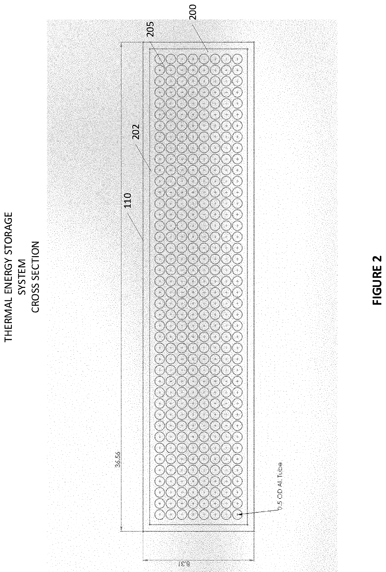
[0091]A thermal energy storage system is made that is capable of cooling a laser weapon that outputs 100 kW of heat. In this example, the laser outputs bursts of energy over a 120 second period and then stays deactivated for 280 seconds. The thermal energy storage system uses an enclosure that contains heat transfer tubes of potassium fluoride tetrahydrate as the phase change material. A 100 kW heat load from a laser that is active over a 120 second period generates 12,000 kJ of heat energy that needs to be dissipated. Potassium fluoride tetrahydrate is able to store 230 kJ / kg of material, thus the thermal energy storage system is made from 52.2 kg of potassium fluoride tetrahydrate to absorb 12,000 kJ of heat energy.

[0092]The material density of potassium fluoride tetrahydrate is 1455 kg / m3 so that 52.1 kg of material requires a volume of 0.0359 m3 of space within the heat transfer tubes located inside the thermal energy storage system enclosure.

[0093]A vapor compression system wit...


PUM


Abstract

Disclosed are systems and methods of flexibly cooling thermal loads by providing a thermal energy storage cooling system for burst mode cooling and a vapor compression system for additional and ancillary cooling to efficiently maintain and cool a thermal load such as from a directed energy weapon system.

Description

CROSS-REFERENCE TO RELATED APPLICATIONS[0001]This application claims priority to U.S. Provisional Application No. 63 / 101,209 entitled “COOLING SYSTEM WITH THERMAL STORAGE” filed on Apr. 13, 2020, the entirety of which is hereby incorporated by reference in its entirety.BACKGROUNDField of the Invention[0002]This disclosure relates generally to a thermal energy storage cooling system that is useful to cool systems that output bursts of heat. In particular, the system may include a thermal energy storage system that uses a salt hydrate as a phase change material to cool bursts of heat from a directed energy weapons system.Description of the Related Art[0003]Conventional vapor compression systems may be efficient at cooling environmental loads, such as rooms or systems with relatively slow gains in heat. However, these systems alone do not generally provide the rapid cooling features necessary to cool a system that outputs bursts of heat. A vapor compression system may take up to a minu...

Claims


Application Information

Patent Timeline
IPC IPC(8): F28D20/02F25B1/00
CPCF28D20/02F25B1/00C09K5/063F28D20/021F28D20/023F28D2021/0028F41H13/005H01S3/04F25B2339/047F25B25/005F25B2400/24Y02E60/14
Inventor KHALILI, KAVEHROCKENFELLER, UWE
Owner ROCKY RES
Why Eureka
Try Eureka